
Concept explainers
Videos
Solve Probs. 7.5 and 7.9, using Mohr's circle.
7.5 through 7.8 For the given state of stress, determine (a) the principal planes, (b) the principal stresses.
7.9 through 7.12 For the given state of stress, determine (a) the orientation of the planes of maximum in-plane shearing stress, (b) the maximum in-plane shearing stress, (c) the corresponding normal stress.
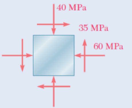
Fig. P7.5 and P7.9
(a)
The principal planes of the state of stress using Mohr’s circle.
Answer to Problem 31P
The principal planes of the state of stress using Mohr’s circle is
Explanation of Solution
Given information:
The stress component along x direction
The stress component along y direction
The shear stress component
Calculation:
Apply the procedure to construct the Mohr’s circle as shown below.
- Find the center of the circle C located
- Plot the reference points A having coordinates
- Connect the point A with C and from the shaded triangle and find the radius R of the circle.
- Sketch the circle once R has been determined.
Construct the Mohr’s circle as shown below.
Calculate the centre of the circle
Substitute
The centre of the circle is
Coordinates of the reference point X.
Substitute
Coordinates of the reference point Y.
Substitute
Calculate the radius (R) of the circle as shown below.
Substitute
Sketch the Mohr’s circle as shown in Figure 1.
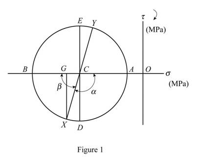
Refer to Figure 1.
Calculate the angle
Calculate the angle
Here,
Substitute
Calculate the principal plane
Substitute
Calculate the principal planes
Substitute
Hence, the principal planes of the state of stress using Mohr’s circle is
(b)
The principal stresses of the state of stress using Mohr’s circle.
Answer to Problem 31P
The maximum principal stress is
The minimum principal stress is
Explanation of Solution
Given information:
The stress component along x direction
The stress component along y direction
The shear stress component
Calculation:
Refer to part (a).
The average stress is
The radius of the Mohr’s circle is
Calculate the principal stresses
Substitute
Calculate the maximum principal stress as shown below.
Hence, the maximum principal stress is
Calculate the minimum principal stress as shown below.
Hence, the minimum principal stress is
(a’)
The orientation of the planes of maximum in-plane shearing stress using Mohr’s circle.
Answer to Problem 31P
The orientation of the planes of maximum in-plane shearing stress is
Explanation of Solution
Given information:
The stress component along x direction
The stress component along y direction
The shear stress component
Calculation:
Refer to part (a).
The principal planes
Calculate the orientation of the planes of maximum in-plane shearing stress
Substitute
Calculate the orientation of the planes of maximum in-plane shearing stress
Substitute
Hence, the orientation of the planes of maximum in-plane shearing stress is
(b’)
The maximum in-plane shearing stress using Mohr’s circle.
Answer to Problem 31P
The maximum in-plane shearing stress is
Explanation of Solution
Given information:
The stress component along x direction
The stress component along y direction
The shear stress component
Calculation:
Refer to part (a).
The maximum in-plane shearing stress is
Hence, the maximum in-plane shearing stress is
(c)
The normal stress using Mohr’s circle.
Answer to Problem 31P
The normal stress is
Explanation of Solution
Given information:
The stress component along x direction
The stress component along y direction
The shear stress component
Calculation:
Refer to part (a).
The average normal stress is
Calculate the normal stress
Substitute
Therefore, the normal stress is
Want to see more full solutions like this?
Chapter 7 Solutions
Mechanics of Materials, 7th Edition


- The storage tank shown contains liquefied propane under a pressure of 1.4 MPa at a temperature of 38 °C . Knowing that the tank has a diameter of 315 mm and a wall thickness of 2.8 mm determinethe maximum normal stress and the maximum shearing stress in the tank.arrow_forwardAt a point in a stressed body, the cartesian components of stress are sigma xx = 60 MPa, sigma yy= -40 MPa, sigma zz = 20 MPa, tau xy = -40 MPa, tau yz = 20 MPa, and tau zx= 30 MPa. Determine: (a) The normal and shear stresses on a plane whose outer normal has the following direction cosines: cos (n, x) = 0.429 ; cos (n, y) = 0.514; cos (n, z) = 0.743arrow_forwardFor the given state of stress, determine (a) the orientation of the planes of maximum in-plane shearing stress, (b) the maximum in-plane shearing stress, (c) the corresponding normal stress.arrow_forward
- For the state of plane stress shown, use Mohr’s circle to determine (a) the largest value of τxy for which the maximum in-plane shearing stress is equal to or less than 12 ksi, (b) the corresponding principal stresses.arrow_forwardA spherical gas container made of steel has a 20-ft outer diameter and a wall thickness of 7/16 in. Knowing that the internal pressure is 75 psi, determine the maximum normal stress and the maximum shearing stress in the container.arrow_forwardA steel pipe of 400-mm outer diameter is fabricated from 10-mm-thick plate by welding along a helix that forms an angle of 20°with a plane perpendicular to the axis of the pipe. Knowing that the maximum allowable normal and shearing stresses in the directions respectively normal and tangential to the weld are σ = 60 MPa and τ = 36 MPa, determine the magnitude P of the largest axial force that can be applied to the pipe.arrow_forward
- At a temperature of 28.75 °C a 0.4-mm gap exists between the ends of the rods shown. At a later time when the temperature has reached 123.11°C, determine the magnitude of the normal stress (in MPa) in the steel rod if L = 306.57 mm and M = 203 mm. Round off the final answer to four decimal places.arrow_forwardA single horizontal force P with a magnitude of 150 lb is applied to end Dof lever ABD. Knowing that portion AB of the lever has a diameter of 1.2 in., determine (a) the normal and shearing stresses located at point H and having sides parallel to the x and y axes, (b) the principal planes and princi-pal stresses at point H.arrow_forwardSuppose that σx = 42 MPa . A) Determine the orientation of principal planes of stress. B) Determine the orientation of the planes of maximum in-plane shear stress.arrow_forward
- For the truss and loading shown, determine the magnitude of the normal stress(in psi) in member CE, knowing that the cross-sectional area of that member is 3.67 in2 if P = 30505 lb, Q = 34758 lb, and y = 7.35 ft. Round off the final answer to two decimal places.arrow_forwardA torque of magnitude T=12 kN·m is applied to the end of a tank containing compressed air under a pressure of 8 MPa. Knowing that the tank has a 180-mm inner diameter and a 12-mm wall thickness, determine the maximum normal stress and the maximum in-plane shearing stress in the tank.arrow_forwardThe cylindrical tank AB has an 8-in. inner diameter and a 0.32-in. wall thickness. Knowing that the pressure inside the tank is 600 psi, deter-mine the maximum normal stress and the maximum in-plane shearing stress at point K.Solve assuming that the 9-kip force applied at point D is directed vertically downwararrow_forward
 Elements Of ElectromagneticsMechanical EngineeringISBN:9780190698614Author:Sadiku, Matthew N. O.Publisher:Oxford University Press
 Mechanics of Materials (10th Edition)Mechanical EngineeringISBN:9780134319650Author:Russell C. HibbelerPublisher:PEARSON
 Thermodynamics: An Engineering ApproachMechanical EngineeringISBN:9781259822674Author:Yunus A. Cengel Dr., Michael A. BolesPublisher:McGraw-Hill Education
 Control Systems EngineeringMechanical EngineeringISBN:9781118170519Author:Norman S. NisePublisher:WILEY
 Mechanics of Materials (MindTap Course List)Mechanical EngineeringISBN:9781337093347Author:Barry J. Goodno, James M. GerePublisher:Cengage Learning
 Engineering Mechanics: StaticsMechanical EngineeringISBN:9781118807330Author:James L. Meriam, L. G. Kraige, J. N. BoltonPublisher:WILEY