For the circuit in Fig. 8.58, the capacitor voltage at t = 0 − (just before the switch is closed) is: (a) 0 V (b) 4 V (c) 8 V (d) 12 V Figure 8.58 For Review Questions 8.1 and 8.2.
For the circuit in Fig. 8.58, the capacitor voltage at t = 0 − (just before the switch is closed) is: (a) 0 V (b) 4 V (c) 8 V (d) 12 V Figure 8.58 For Review Questions 8.1 and 8.2.
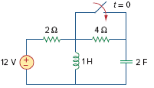
For the circuit in Fig. 8.58, the capacitor voltage at t = 0− (just before the switch is closed) is:
(a) 0 V
(b) 4 V
(c) 8 V
(d) 12 V
Figure 8.58
For Review Questions 8.1 and 8.2.
Expert Solution & Answer
To determine
Choose the correct option to find the capacitor voltage at t=0− (just before the switch is closed).
Answer to Problem 1RQ
The correct option form the given choices is (a) 0 V.
Explanation of Solution
Calculation:
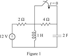
Redraw the given circuit as shown in Figure 1.
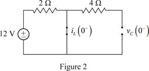
For the DC circuit, at the steady state condition when switch is open at t=0−, the capacitor acts as open circuit and the inductor act as short circuit. Therefore, the Figure 1 becomes as shown in Figure 2.
Since, the capacitor is open circuited, the voltage across the capacitor at t=0− is 0 V.
Therefore, the capacitor voltage at t=0− is vC(0−).
vC(0−)=0V
Therefore, the option (a) is correct and the options (b), (c), (d) are incorrect.
Conclusion:
Thus, the correct option from the given choices is (a) 0 V.
Want to see more full solutions like this?
Subscribe now to access step-by-step solutions to millions of textbook problems written by subject matter experts!
For the two-source circuit of Fig. 8.89, note that one source is always on. (a) Obtain an expression for i(t) valid for all t; (b) determine at what time the energy stored in the inductor reaches 99 percent of its maximum value.
The resistance, inductance, and capacitance in a parallel RLC circuit in (Figure 1) are 0.4 kΩ, 5 H, and 5 μF, respectively.Calculate the minimum root of the characteristic equation that describes the voltage response of the circuitCalculate the maximum root of the characteristic equation that describes the voltage response of the circuit.
Principles and Applications of Electrical Engineering
Knowledge Booster
Learn more about
Need a deep-dive on the concept behind this application? Look no further. Learn more about this topic, electrical-engineering and related others by exploring similar questions and additional content below.
ENA 9.2(1)(En)(Alex) Sinusoids & Phasors - Explanation with Example 9.1 ,9.2 & PP 9.2; Author: Electrical Engineering Academy;https://www.youtube.com/watch?v=vX_LLNl-ZpU;License: Standard YouTube License, CC-BY
Electrical Engineering: Ch 10 Alternating Voltages & Phasors (8 of 82) What is a Phasor?; Author: Michel van Biezen;https://www.youtube.com/watch?v=2I1tF3ixNg0;License: Standard Youtube License


 Introductory Circuit Analysis (13th Edition)Electrical EngineeringISBN:9780133923605Author:Robert L. BoylestadPublisher:PEARSON
 Delmar's Standard Textbook Of ElectricityElectrical EngineeringISBN:9781337900348Author:Stephen L. HermanPublisher:Cengage Learning
 Programmable Logic ControllersElectrical EngineeringISBN:9780073373843Author:Frank D. PetruzellaPublisher:McGraw-Hill Education
 Fundamentals of Electric CircuitsElectrical EngineeringISBN:9780078028229Author:Charles K Alexander, Matthew SadikuPublisher:McGraw-Hill Education
 Electric Circuits. (11th Edition)Electrical EngineeringISBN:9780134746968Author:James W. Nilsson, Susan RiedelPublisher:PEARSON
 Engineering ElectromagneticsElectrical EngineeringISBN:9780078028151Author:Hayt, William H. (william Hart), Jr, BUCK, John A.Publisher:Mcgraw-hill Education,