
Videos
The switch in Fig. 8.77 moves from position A to position B at t = 0 (please note that the switch must connect to point B before it breaks the connection at A, a make-before-break switch). Determine i(t) for t > 0.
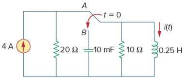
Figure 8.77
For Prob. 8.24.
Find the expression of current
Answer to Problem 24P
The expression of current
Explanation of Solution
Formula used:
Write an expression to calculate the neper frequency for a parallel
Here,
Write an expression to calculate the neper frequency for a parallel
Here,
The three types of responses of the parallel
- i. When
- ii. When
- iii. When
Write a general expression to calculate the voltage response of parallel
Here,
Write an expression to calculate the damped natural frequency.
Calculation:
The given circuit is redrawn as shown in Figure 1.
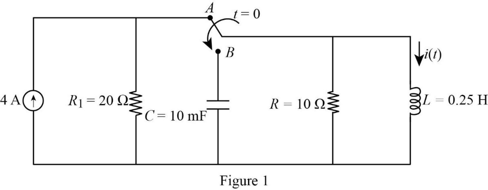
For a DC circuit, at steady state condition when time
Refer to Figure 2, the short circuited inductor, resistors
Since the inductor is short circuit, the total current flows through the inductor.
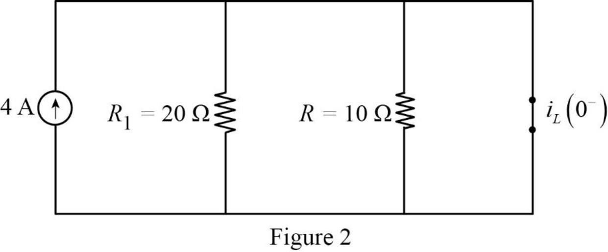
The Figure 2 is reduced as shown in Figure 3.
Refer to Figure 3, the current through inductor is,
The voltage across the capacitor is,
The current through inductor and voltage across the capacitor is always continuous so that,
For time
Substitute
Substitute
Comparing the value of neper and natural frequency, the value of neper frequency is less than natural frequency
Substitute
Substitute
Substitute
Substitute
Substitute
Differentiate equation (7) with respect to
Substitute
Apply Kirchhoff’s current law for Figure 3.
Substitute
Substitute
Substitute
Simplify the above equation to find
Substitute
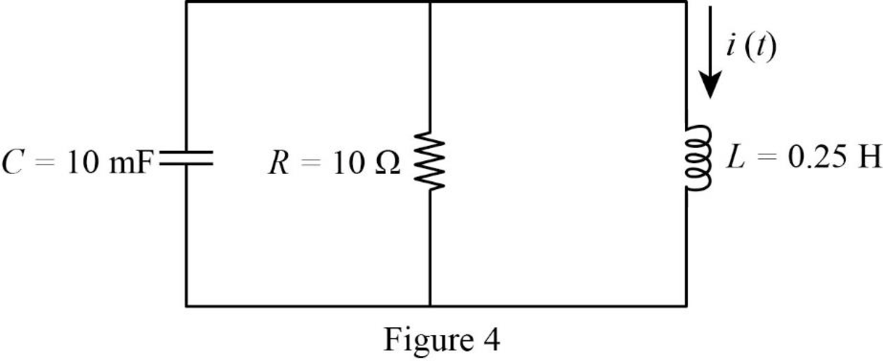
For the parallel
Refer to Figure 4, the current
Write an expression to calculate the current through inductor.
Substitute
Assume,
Substitute
Use integration by parts,
Assume
Simplify the above equation to find
Write an expression to calculate the integration by parts.
Substitute
Assume,
Substitute
Assume,
Simplify the above equation to find
Substitute
Substitute
Substitute
Simplify the above equation to find
Substitute
Substitute
Conclusion:
Thus, the expression of current
Want to see more full solutions like this?
Chapter 8 Solutions
Fundamentals of Electric Circuits


- Show the comparison between the 2nd order damped spring model and the 2nd RLC circuit system.arrow_forwardExplain briefly the terms (i) overdamped (ii) critically-damped, and (iii) underdamped in context with RLC circuits.arrow_forwardSelect such state variables for the above RLC circuit so that the state equations of the system can be written in the form x = Ax +Bu , y=Cx+Du. Show it.arrow_forward
- A system is described by the following differential equation:arrow_forwardFind the state variables of the above given RLC circuit such that the state equations of the system x= Ax+Bu Y= Cx + Duarrow_forwardThe current in an RLC circuit is described by the equation d^2/dt+7di/dt+12i=0.determine i(t) for t>0 if the initial condition of the circuit is=i(0)=2.5mA and di(0)/dt=0,the values of R,L,C and the voltage across each element and sketch the circuitarrow_forward
- An RL circuit has an emf of 5V, a resistance of 50 Ω, an inductance of 1 H, and no initial current.Find the current in the circuit at any time, t.arrow_forward28.1. Define source-free series RLC circuit in two sentences. 28.2. Enumerate five step-by-step procedures in solving source-free series RLC circuit. 28.3. Enumerate five applications of source-free series RLC circuit.arrow_forwardIn the following RLC circuit, the switch was in position ‘a’ for t<0. At t=0 the switchis moved to position ‘b’. Find the expression for v c (t) for ≥ 0arrow_forward
- For a series RLC circuit, if R =30 Ω and L = 1.5 H, then ( i ) an RLC circuit will be overdamped when C >,< or = ______ mF. ( ii ) an RLC circuit will be critically damped when C >,< or = ______ mF. ( iii ) an RLC circuit will be underdamped when C <,>or = ______ mF.arrow_forwardSelect such state variables for the RLC circuit shown in the figure so that the system can be written in the form of state equations (x and y equations in the figure).arrow_forwardAt time t = 0 because of closing a switch, an RL circuit in series has resistance R = 50Ω andinductance L = 10H with a constant supply of V = 100V. It is desired to find the current at 0.5seconds, after finding the differential equation for the current.arrow_forward
 Introductory Circuit Analysis (13th Edition)Electrical EngineeringISBN:9780133923605Author:Robert L. BoylestadPublisher:PEARSON
 Delmar's Standard Textbook Of ElectricityElectrical EngineeringISBN:9781337900348Author:Stephen L. HermanPublisher:Cengage Learning
 Programmable Logic ControllersElectrical EngineeringISBN:9780073373843Author:Frank D. PetruzellaPublisher:McGraw-Hill Education
 Fundamentals of Electric CircuitsElectrical EngineeringISBN:9780078028229Author:Charles K Alexander, Matthew SadikuPublisher:McGraw-Hill Education
 Electric Circuits. (11th Edition)Electrical EngineeringISBN:9780134746968Author:James W. Nilsson, Susan RiedelPublisher:PEARSON
 Engineering ElectromagneticsElectrical EngineeringISBN:9780078028151Author:Hayt, William H. (william Hart), Jr, BUCK, John A.Publisher:Mcgraw-hill Education,