
Concept explainers
Videos
The switch in Fig. 8.70 is moved from A to B at t = 0 after being at A for a long time. This places the two capacitors in series, thus allowing equal and opposite dc voltages to be trapped on the capacitors. (a) Determine v1(0−), v2(0−), and vR(0−). (b) Find v1(0+), v2(0+), and vR(0+). (c) Determine the time constant of vR(t). (d) Find vR(t), t > 0. (e) Find i(t). (f) Find v1(t) and v2(t) from i(t) and the initial values. (g) Show that the stored energy at t = ∞ plus the total energy dissipated in the 20 kΩ resistor is equal to the energy stored in the capacitors at t = 0.
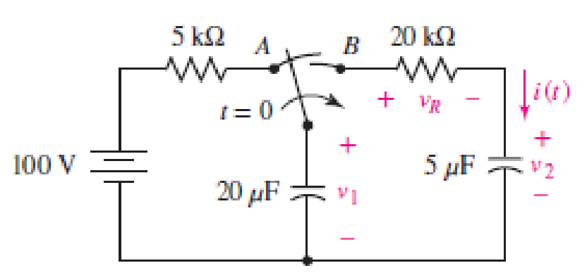
■ FIGURE 8.70
(a)
Find the value of
Answer to Problem 38E
The value of
Explanation of Solution
Given data:
Refer to Figure 8.70 in the textbook.
The switch is moved from
Calculation:
The given circuit is redrawn as shown in Figure 1.
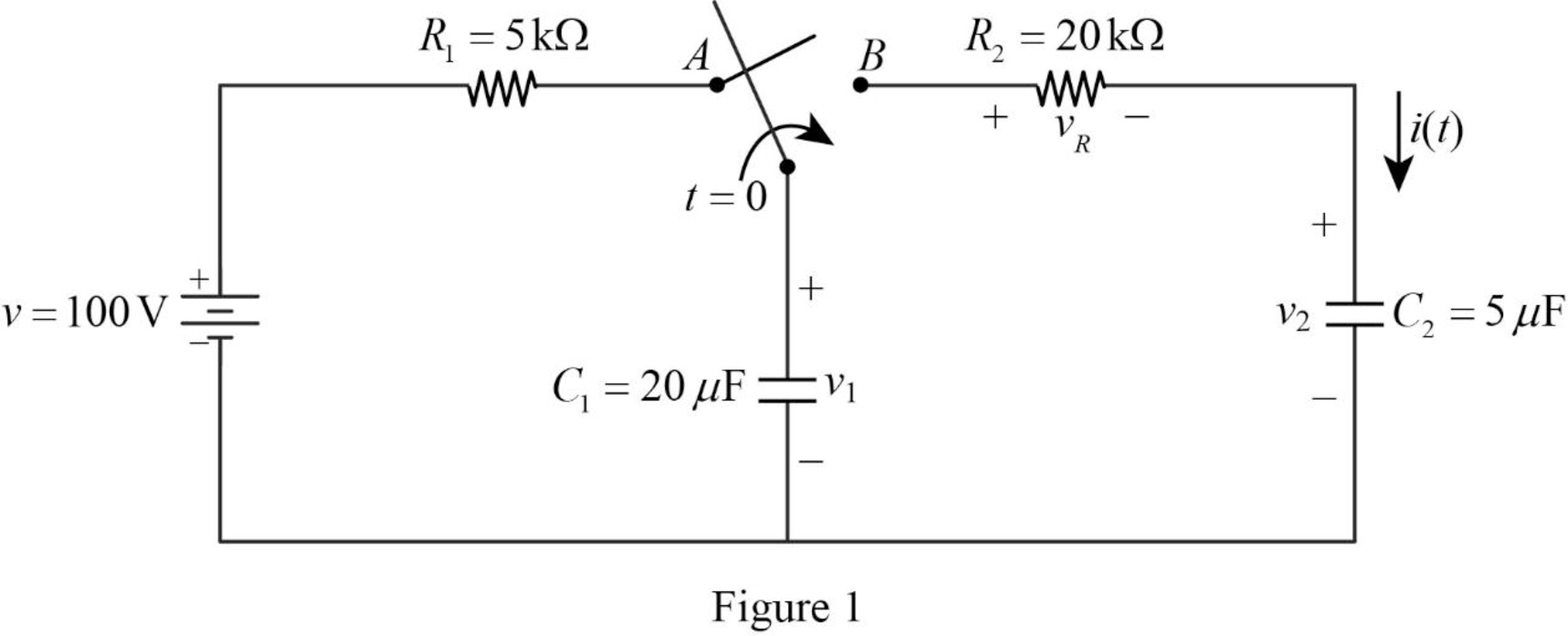
Refer to Figure 1, the voltage across the capacitor
For a DC circuit at steady state condition, when the switch is in position
Now, the Figure 1 is reduced as shown in Figure 2.
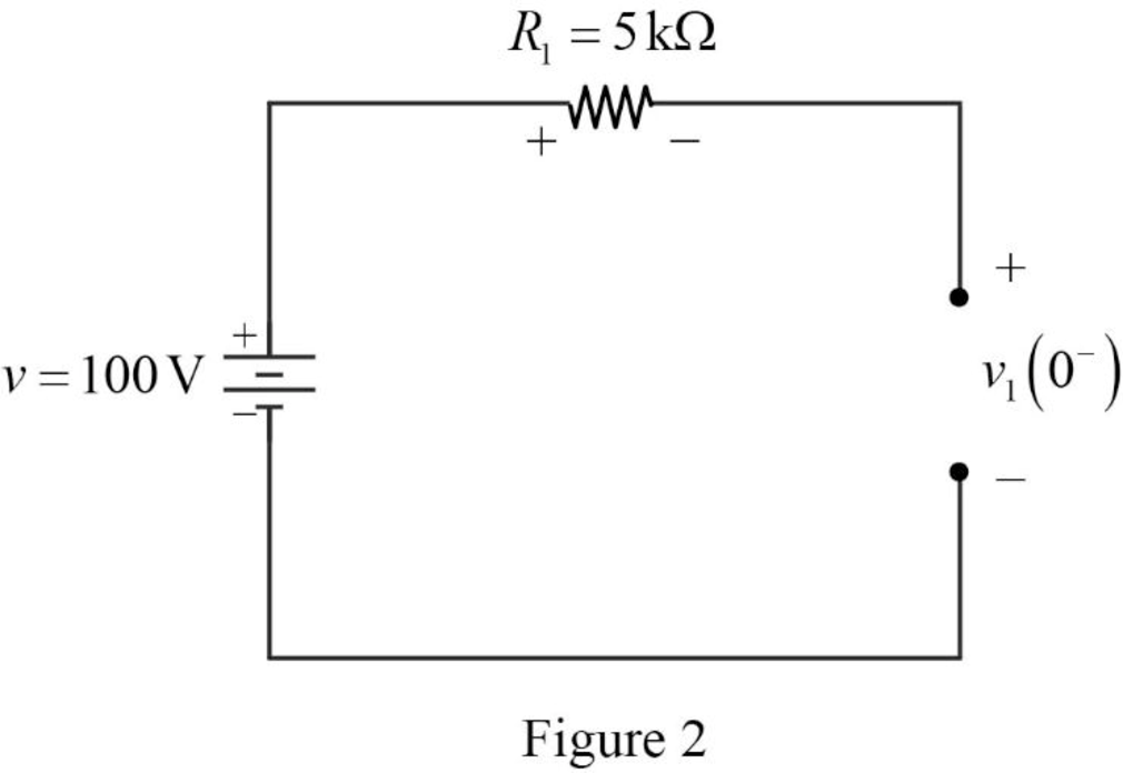
Refer to Figure 2, the voltage source
The voltage across the capacitor
Refer to Figure 2, the resistor
The voltage across the capacitor is always continuous so that,
Conclusion:
Thus, the value of
(b)
Find the value of
Answer to Problem 38E
The value of
Explanation of Solution
Calculation:
For time
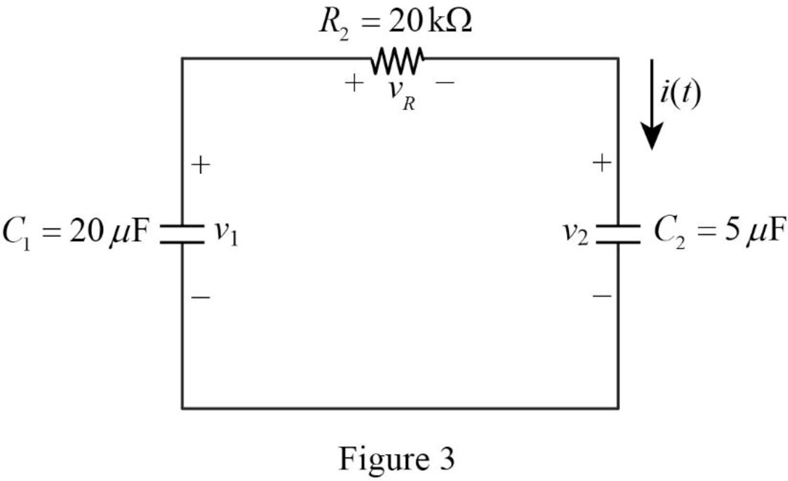
Refer to part (a),
Apply Kirchhoff’s voltage for the circuit shown in Figure 3 for time
Substitute
Conclusion:
Thus, the value of
(c)
Find the value of the time constant.
Answer to Problem 38E
The value of time constant
Explanation of Solution
Formula used:
Write a general expression to calculate the time constant.
Here,
Calculation:
Refer to Figure 3, the capacitors
The equivalent capacitance
Now, the Figure 3 is reduced as shown in Figure 4.
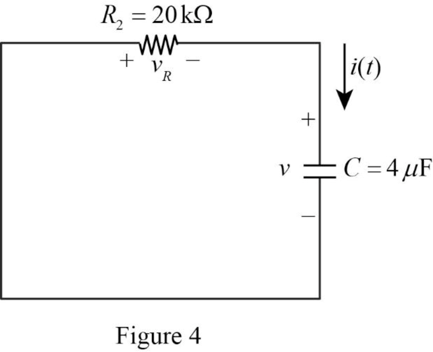
Refer to Figure 4, it shows the
Use equation (1) to find
Substitute
Conclusion:
Thus, the value of time constant
(d)
Find the expression of voltage
Answer to Problem 38E
The expression of voltage
Explanation of Solution
Formula used:
Write a general expression to calculate the voltage response of an
Here,
Refer to Figure 3, the resistor
Substitute
Substitute
Conclusion:
Thus, the expression of voltage
(e)
Find the expression of current
Answer to Problem 38E
The expression of current
Explanation of Solution
Calculation:
Refer to Figure 3, the capacitor
The current
Substitute
Conclusion:
Thus, the expression of current
(f)
Find the value of voltage
Answer to Problem 38E
The value of voltage
Explanation of Solution
Formula used:
Write a general expression to calculate the voltage across the capacitor.
Calculation:
From the given data, the capacitor
Use equation (1) to find the voltage
Substitute
Simplify the above equation to find
Use equation (1) to find the voltage
Substitute
Simplify the above equation to find
Conclusion:
Thus, the value of voltage
(g)
Show that the stored energy at
Explanation of Solution
Formula used:
Write a general expression to calculate the energy stored in a capacitor.
Write a general expression to calculate the energy stored in a resistor.
Here,
Calculation:
Refer to Figure 1, there are two capacitors placed in a circuit. Therefore, the total energy stored in a capacitor is,
Use equation (1) to find
Use equation (1) to find
Substitute equation (7) and (8) in (6).
Substitute
Substitute
Simplify the above equation to find
Refer to part (f),
Substitute
Refer to part (f),
Substitute
Substitute
Substitute
Simplify the above equation to find
Substitute
Simplify the above equation to find
Simplify the above equation to find
Substitute
Add
Therefore,
Therefore, the stored energy at
Conclusion:
Thus, the stored energy at
Want to see more full solutions like this?
Chapter 8 Solutions
Loose Leaf for Engineering Circuit Analysis Format: Loose-leaf


- Suppose the input to the circuit is a damped ramp of the form Kte−100t V. Find the largest value of K such that the inductor current does not exceed the 40 mA current ratingarrow_forwardCalculate initial conditions for inductor current and capacitor voltage in circuit presented in Fig. 8.3. Assume: L=1H, C=0.5F, R=1Ω, e(t) = 10 2 sin(t + 45 ) V, i(t) = 2sin(t − 45 ) A.arrow_forward1) The circuit shown below is initially, for t < 0, with capacitor C connected to a battery (Vbat = 12 V).The key is switched at t = 0, disconnecting the battery and turning on the capacitor to the rest of the circuit.a)Calculate the circuit current in the time domain, i(t).b) In practice, after how long can the energy stored in the circuit be considered to be irrelevant (close to zero)?arrow_forward
- For the circuit shown in Fig 8, find i, vc, and iL, as well as the energy accumulated in the capacitor and inductor.arrow_forwardA series circuit has a capacitor of 1.5625x10^(-8)F a resistor of 2x10^4 ohms, and an inductor of 1H. If the initial charge on the capacitor is zero,. if a 12-volt battery is connected to the circuit and the circuit is closed at t=0, determine the charge on the capacitor at any time tarrow_forwardFor the circuit below with the switch closed and then opening at t=0, and R1= 3Ω, R2= 7Ω, C = 0.2H, ig = 8A, vs = 2v, calculate the initial condition. Develop the differential equation for the solution for t > 0. Calculate the current ia(t) for all times.arrow_forward
- *The resistance, inductance, and capacitance in a parallel RLC circuit are 1900 Ω , 250 mH , and 9 nF , respectively. * Pt A. Calculate the minimum root of the characteristic equation that describes the voltage response of the circuit. Pt B. Calculate the maximum root of the characteristic equation that describes the voltage response of the circuit. Pt C.Will the response be over-, under-, or critically damped? Pt D. What value of R will yield a damped frequency of 12 krad/s? Pt E. What are the roots of the characteristic equation for the value of R found in Part D? Pt F. What value of R will result in a critically damped response?arrow_forwardThe circuit elements in the circuit L=50 mH, and C=0.2 μF. The initial inductor current is−45 mA and the initial capacitor voltage is 15 V.4. The resistance is increased to 312.5 Ω. Find the expression for v(t) for t≥0.arrow_forwardThe switch in the circuit shown in the figure below has been open for a long time. It closes at t = 0s, then 1-Calculate the initial stored energy in the capacitor 2- Find the current iR(t) for t >= 0. 3- Plot the current iR(t) for t >= 0.arrow_forward
- The resistance, inductance, and capacitance in a parallel RLC circuit in (Figure 1) are 0.4 kΩ, 5 H, and 5 μF, respectively.Calculate the minimum root of the characteristic equation that describes the voltage response of the circuitCalculate the maximum root of the characteristic equation that describes the voltage response of the circuit.arrow_forwarddifferential equations applications. A 12-volt battery is connected to a series circuit in which the inductor is 1/2 henry and the resistance is 10 ohms. Determine current i, if the initial current is zero.arrow_forwardThe circuit elements in the circuit L=50 mH, and C=0.2 μF. The initial inductor current is−45 mA and the initial capacitor voltage is 15 V. The resistance is increased to250 Ω. Find the expression for v(t) for t≥0.arrow_forward
 Introductory Circuit Analysis (13th Edition)Electrical EngineeringISBN:9780133923605Author:Robert L. BoylestadPublisher:PEARSON
 Delmar's Standard Textbook Of ElectricityElectrical EngineeringISBN:9781337900348Author:Stephen L. HermanPublisher:Cengage Learning
 Programmable Logic ControllersElectrical EngineeringISBN:9780073373843Author:Frank D. PetruzellaPublisher:McGraw-Hill Education
 Fundamentals of Electric CircuitsElectrical EngineeringISBN:9780078028229Author:Charles K Alexander, Matthew SadikuPublisher:McGraw-Hill Education
 Electric Circuits. (11th Edition)Electrical EngineeringISBN:9780134746968Author:James W. Nilsson, Susan RiedelPublisher:PEARSON
 Engineering ElectromagneticsElectrical EngineeringISBN:9780078028151Author:Hayt, William H. (william Hart), Jr, BUCK, John A.Publisher:Mcgraw-hill Education,