
Videos
(a)
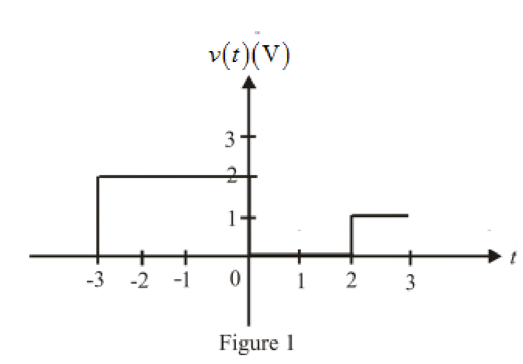
Sketch the functions over the range
(a)
Explanation of Solution
Given data:
The given function is:
The range of
Calculation:
The unit-step forcing function as a function of time which is zero for all values of its argument less than zero and which is unity for all positive values of its argument.
Here,
Substitute
Substitute
Substitute
Substitute
Substitute
Substitute
Substitute
The different value of the function
The sketch of the function over the range
Conclusion:
Thus, the sketch for the function over the range
(b)
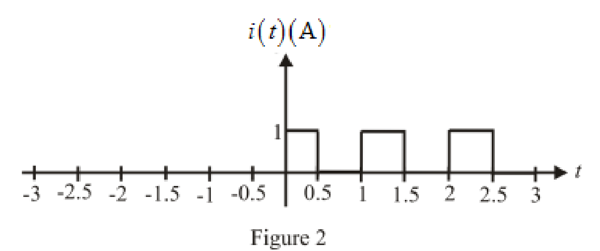
Sketch the functions over the range
(b)
Explanation of Solution
Given Data:
The function is
The range of
Calculation:
The unit-step forcing function as a function of time which is zero for all values of its argument less than zero and which is unity for all positive values of its argument.
Here,
Substitute
Substitute
Substitute
Substitute
Substitute
Substitute
Substitute
Substitute
Substitute
Substitute
The different value of the function
The sketch of the function over the range
Conclusion:
Thus, the sketch for the function over the range
(c)
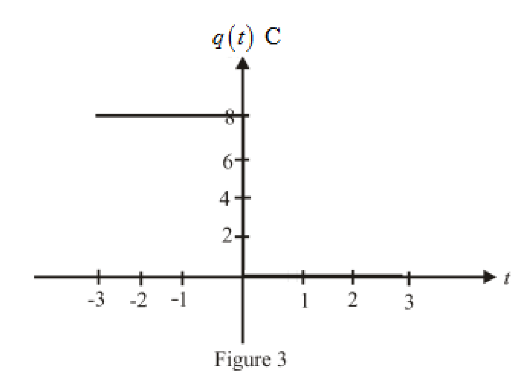
Sketch the functions over the range
(c)
Explanation of Solution
Given data:
The function is
The range of
Calculation:
The unit-step forcing function as a function of time which is zero for all values of its argument less than zero and which is unity for all positive values of its argument.
Here,
Substitute
Substitute
Substitute
Substitute
Substitute
Substitute
Substitute
The different value of the function
The sketch the function over the range
Conclusion:
Thus, the sketch for the function over the range
Want to see more full solutions like this?
Chapter 8 Solutions
Loose Leaf for Engineering Circuit Analysis Format: Loose-leaf


- The mathematical models of some continuous time systems are given above. x(t) is the input signal of the system, and y(t) is the output signal of the system. Which of the following systems is linear and which is nonlinear? For linear systems, write "linear" in the space next to the option. For non-linear systems, write "non-linear" in the space next to the option.arrow_forwardStep functions can be used to define a window function. Thusu(t −1)−u(t−4) defines a window 1 unit high and 3 units wide located on the time axis between 1 and 4. A function f(t) is defined as follows: f(t)=0,t≤0;=−20t,0≤t≤1 s= −20,1 s≤t≤2 s=2 cosπ2t,2 s≤t≤4 s;=100−20t,4 s≤t≤5 s=0,5 s≤t<∞. 1. Sketch f(t) over the interval −1 s≤t≤6 s. 2. Use the concept of the window function to write an expression for f(t).arrow_forwardWhen the unit step function is applied to the input of the system whose block diagram is given below, the output response takes the value c (0.2) = 0.11 for t = 0.2 s and c (infinity) = 0.333 for t = infinity. What is the steady-state error of the system? calculate.arrow_forward
- When the unit step function is applied to the system input whose block diagram is given below, the output response is c(0.2) = 0.11 for t=0.2 s, and c(infinity)=0.333 for t=infinity. What is the settling time of the system? calculate.arrow_forward3. (a) Find the characteristic polynomial, characteristic equation, characteristic roots, and characteristic modes of this system. (b) Find y(t) the zero-input component of the response for t >= 0, if the initial conditions are y(0) = 1 and y'(0)= -2 for [(D^2)+4D+8]y(t) = Dx(t)arrow_forwardThe mathematical models of some continuous time systems are given above. x(t) is the input signal of the system, and y(t) is the output signal of the system. Which of the following systems has fixed parameters and which has variable parameters?arrow_forward
- Plot the step response of the continuous and discrete-time systems:arrow_forwardIf G(s) = 1 / (s + 2), find the response c(t) if the input r(t) = u(t), a unit step, assuming zero initial condition.arrow_forwardQ: In the network of Fig. (1), the switch is closed at t=0 and there is no initial charge on either of the capacitors. Find the resulting current ( i ). (Using Laplace Transform). 100 Fig. 1arrow_forward
- The block diagram of a time-invariant, linear, continuous-time system is given below. X1(s) and X2(s) are the state variables of the system. U(s) is the input signal of the system, Y(s) is the output signal of the system. What is the value of parameter E?arrow_forwardGiven the plant transfer function, G(s) = 90/ s(s+4) and H(s) = 1. Obtain (i) characteristic equation (ii) damped frequency of oscillation (iii) damping ratio (iv) settling time (v) delay timearrow_forward25 - When the unit step function is applied to the system input given the block diagram below, the output response takes the value c (0.2) = 0.11 for t = 0.2 s and c (infinity) = 0.333 for t = infinity. What is the time constant of the system? calculate.A) 0.5 sB) 0.33 sC) 2 sD) 0.25 sE) 1 sarrow_forward
 Power System Analysis and Design (MindTap Course ...Electrical EngineeringISBN:9781305632134Author:J. Duncan Glover, Thomas Overbye, Mulukutla S. SarmaPublisher:Cengage Learning