
Concept explainers
Videos
(a)
Find the expression for
(a)
Answer to Problem 48E
The expression for
Explanation of Solution
Formula used:
The expression for the equivalent resistor when resistors are connected in parallel is as follows:
Here,
The expression for the time constant is as follows:
Here,
The expression for the final response is as follows:
Here,
Calculation:
The redrawn circuit diagram is given in Figure 1.
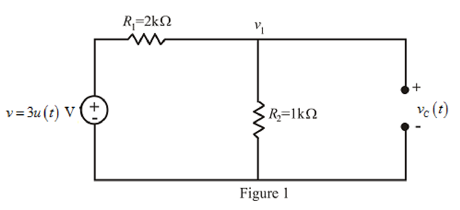
Refer to the redrawn Figure 1:
The given circuit is connected for long time,
So, capacitor behaves as open circuit.
The independent voltage source is unit step function.
The unit-step forcing function as a function of time which is zero for all values of its argument less than zero and which is unity for all positive values of its argument.
Here,
The independent voltage source is:
Substitute
Apply KCL at node 1.
Here,
Substitute
Rearrange for
So, at
The voltage across capacitorat
So,
Substitute
So, the value of the voltage across
Substitute
Rearrange for
So, the voltage
The redrawn circuit diagram is given in Figure 2.
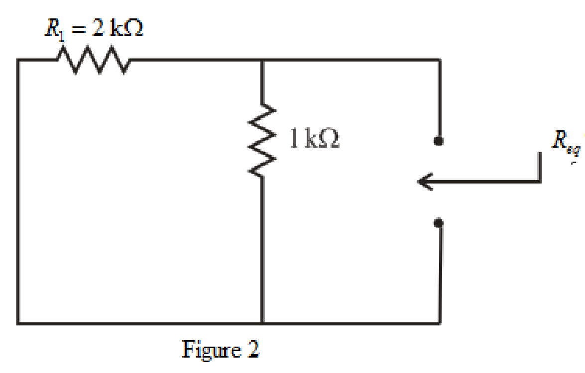
Refer to the redrawn Figure 2:
So, form equation (1),
Rearrange the equation for
The simplified diagram is shown in Figure 3.
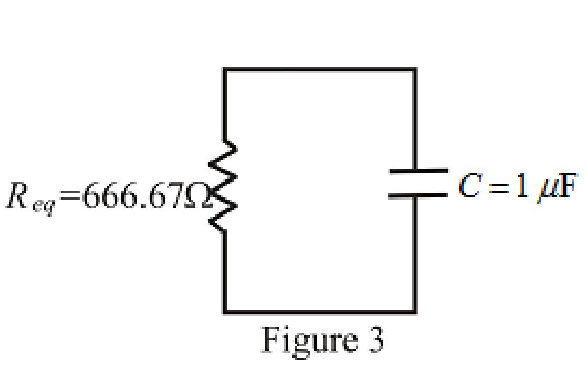
Refer to the redrawn Figure. 3:
Substitute
Substitute
So, the expression for the voltage across the capacitor valid for all values of
Conclusion:
Thus, the expression for
(b)
Sketch
(b)
Explanation of Solution
Given Data:
The range for the time is
Calculation:
Substitute
Substitute
Substitute
Substitute
Substitute
Substitute
Substitute
Substitute
Substitute
The different values of the
The graph for
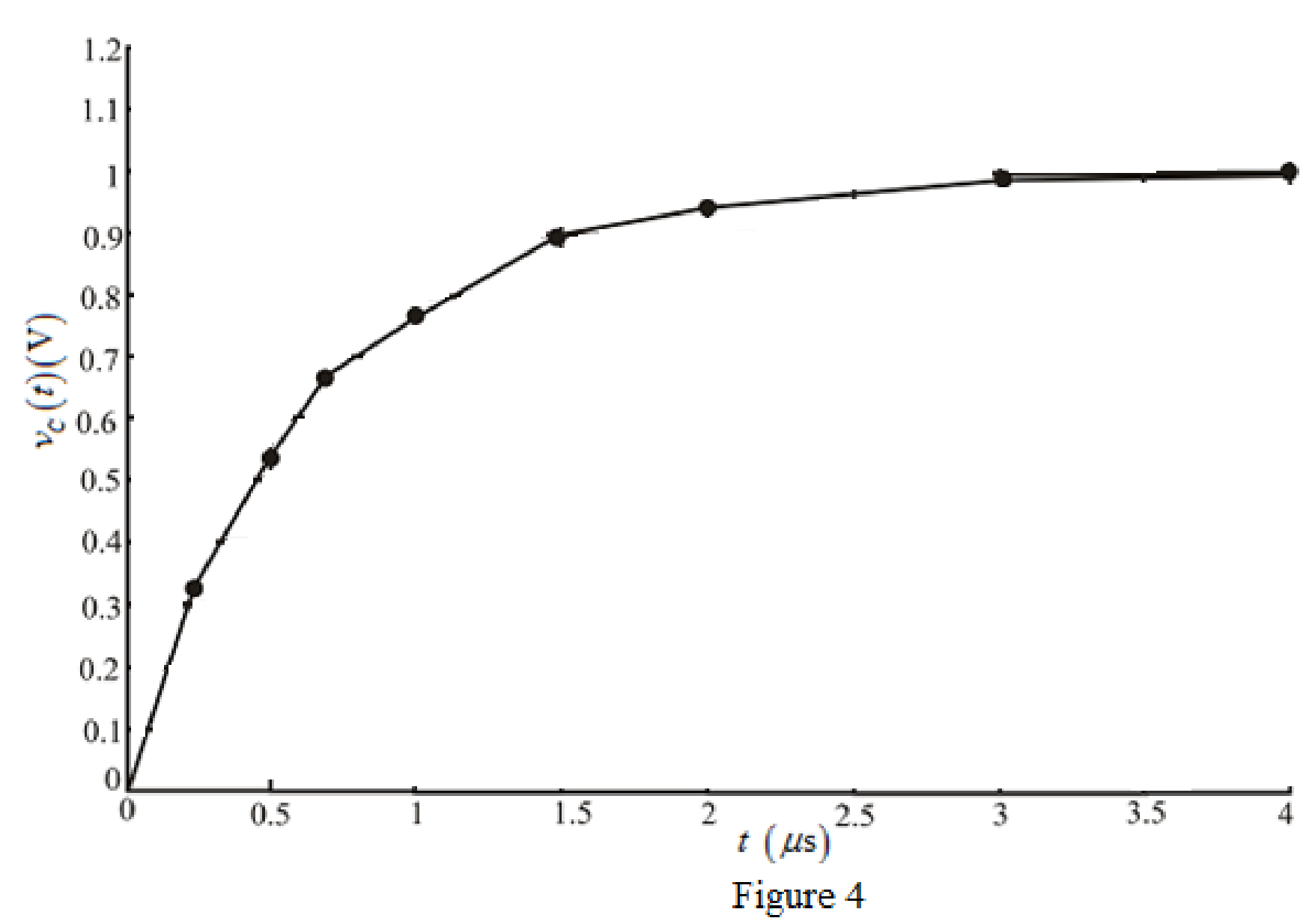
Conclusion:
Thus, the graph for
Want to see more full solutions like this?
Chapter 8 Solutions
Loose Leaf for Engineering Circuit Analysis Format: Loose-leaf


- The switch in Fig. 8.73 is moved from A to B at t = 0 after being at A for a long time. This places the two capacitors in series, thus allowing equal and opposite de voltages to be trapped on the capacitors (d) Find vr(t), t > 0. (e) Find i(t). (f) Find vi(t) and v2(t) from i(t) and the initial values. (g) Show that the stored energy at i = 0 plus the total energy dissipated in the 20 kS2 resistor is equal to the energy stored in the capacitors at t = 0arrow_forwardFor the circuit below with the switch closed and then opening at t=0, and R1= 3Ω, R2= 7Ω, C = 0.2H, ig = 8A, vs = 2v, calculate the initial condition. Develop the differential equation for the solution for t > 0. Calculate the current ia(t) for all times.arrow_forwardSuppose the input to the circuit is a damped ramp of the form Kte−100t V. Find the largest value of K such that the inductor current does not exceed the 40 mA current ratingarrow_forward
- identify the following 1. If the pole’s real value is positive and is located on the right side of the S-plane. The system exponentially ____________.2. Is a continuous connection of branches from one node to another with all arrowheads in the same direction.3. Knowing the location of the pole in the S-plane determines the ______________ of the system.arrow_forwardCalculate the current in an RLC circuit with resistances R=11 ohms, L=0.1 H, and C=10^-2 F that is linked to the source V(t)= 10sin 377t. Assume that the capacitor charge and current are both zero at time t=0.arrow_forward1) The circuit shown below is initially, for t < 0, with capacitor C connected to a battery (Vbat = 12 V).The key is switched at t = 0, disconnecting the battery and turning on the capacitor to the rest of the circuit.a)Calculate the circuit current in the time domain, i(t).b) In practice, after how long can the energy stored in the circuit be considered to be irrelevant (close to zero)?arrow_forward
- The circuit elements in the circuit L=50 mH, and C=0.2 μF. The initial inductor current is−45 mA and the initial capacitor voltage is 15 V. The resistance is increased to250 Ω. Find the expression for v(t) for t≥0.arrow_forwardIf the roots of the characteristic equation are -3,0 then the system is _________________________. Marginally stable Conditionally stable Stable Unstablearrow_forwardThe switch in the circuit shown in the figure below has been open for a long time. It closes at t = 0s, then 1-Calculate the initial stored energy in the capacitor 2- Find the current iR(t) for t >= 0. 3- Plot the current iR(t) for t >= 0.arrow_forward
- The switch in Fig. 8.73 is moved from A to B at t = 0 after being at A for along time. This places the two capacitors in series, thus allowing equal andopposite dc voltages to be trapped on the capacitors. (a) Determine v1(0−),v2(0−), and vR(0−). (b) Find v1(0+), v2(0+), and vR(0+). (c) Determine thetime constant of vR(t). (d) Find vR(t), t > 0. (e) Find i(t). ( f ) Find v1(t) andv2(t) from i(t) and the initial values. (g) Show that the stored energy at t = ∞plus the total energy dissipated in the 20 k-resistor is equal to the energystored in the capacitors at t = 0.arrow_forwardIn the circuit , the resistor isadjusted for critical damping. The initial capacitor voltage is 20 V, andthe initial inductor current is 30 mA.1. Find the numerical value of R.2. Find the numerical values of i and di/dt immediately after theswitch is closed.3. Find vC(t) for t≥0.arrow_forward*Assume that at the instant the 2 A dc current source is applied to the circuit in (Figure 1), the initial current in the 25 mH inductor is 1 A, and the initial voltage on the capacitor is 50 V (positive at the upper terminal).* Pt A. Find the expression for iL(t) for t≥0 if R equals 12.5 Ωarrow_forward
 Introductory Circuit Analysis (13th Edition)Electrical EngineeringISBN:9780133923605Author:Robert L. BoylestadPublisher:PEARSON
 Delmar's Standard Textbook Of ElectricityElectrical EngineeringISBN:9781337900348Author:Stephen L. HermanPublisher:Cengage Learning
 Programmable Logic ControllersElectrical EngineeringISBN:9780073373843Author:Frank D. PetruzellaPublisher:McGraw-Hill Education
 Fundamentals of Electric CircuitsElectrical EngineeringISBN:9780078028229Author:Charles K Alexander, Matthew SadikuPublisher:McGraw-Hill Education
 Electric Circuits. (11th Edition)Electrical EngineeringISBN:9780134746968Author:James W. Nilsson, Susan RiedelPublisher:PEARSON
 Engineering ElectromagneticsElectrical EngineeringISBN:9780078028151Author:Hayt, William H. (william Hart), Jr, BUCK, John A.Publisher:Mcgraw-hill Education,