
Fundamentals of Geotechnical Engineering (MindTap Course List)
5th Edition
ISBN: 9781305635180
Author: Braja M. Das, Nagaratnam Sivakugan
Publisher: Cengage Learning
expand_more
expand_more
format_list_bulleted
Concept explainers
Videos
Textbook Question
Chapter 8, Problem 8.20P
Refer to Figure 8.24. Determine the vertical stress increase, Δσ, at point A with the following values:
q1 = 100 kN/m x1 = 3 m z = 2 m
q2 = 200 kN/m x2 = 2 m
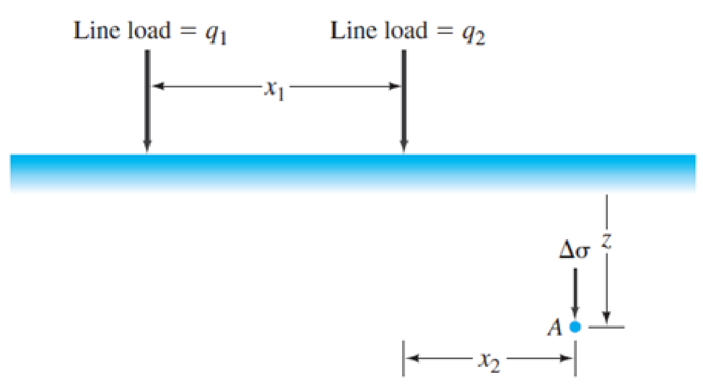
FIG. 8.24 Stress at a point due to two line loads
Expert Solution & Answer

Trending nowThis is a popular solution!

Students have asked these similar questions
Use Eq. (6.14) to determine the stress increase Δσ at z = 10 ft below the center of the area described in Problem 6.5.
Refer to Figure P6.3. Determine the vertical stress increase Δσ at point A with the values q1 = 90 kN/m, q2 = 325 kN/m, x1 = 4 m, x2 = 2.5 m, and z = 3 m.
An earth embankment is shown in Figure 10.44. Determine the stress increase at point A due to the embankment load. Given: β = 25°, γ = 119 lb/ft 3, x = 55 ft, y = 28 ft, and z = 20 ft.
Chapter 8 Solutions
Fundamentals of Geotechnical Engineering (MindTap Course List)
Ch. 8 - Prob. 8.1PCh. 8 - Prob. 8.2PCh. 8 - Prob. 8.3PCh. 8 - Prob. 8.4PCh. 8 - Prob. 8.5PCh. 8 - Prob. 8.6PCh. 8 - Prob. 8.7PCh. 8 - Prob. 8.8PCh. 8 - Prob. 8.9PCh. 8 - The soil profile at a site consists of 10 m of...
Ch. 8 - Prob. 8.11PCh. 8 - Prob. 8.12PCh. 8 - Prob. 8.13PCh. 8 - Prob. 8.14PCh. 8 - A sand has Gs = 2.66. Calculate the hydraulic...Ch. 8 - Prob. 8.16PCh. 8 - A point load of 1000 kN is applied at the ground...Ch. 8 - Point loads of magnitude 9, 18, and 27 kN act at...Ch. 8 - Refer to Figure 8.13. The magnitude of the line...Ch. 8 - Refer to Figure 8.24. Determine the vertical...Ch. 8 - Consider a circularly loaded flexible area on the...Ch. 8 - A flexible circular footing of radius R carries a...Ch. 8 - The plan of a flexible rectangular loaded area is...Ch. 8 - Refer to Figure 8.26. The circular flexible area...Ch. 8 - Refer to Figure 8.27. The flexible area is...Ch. 8 - Prob. 8.26CTPCh. 8 - Prob. 8.27CTP
Knowledge Booster


Learn more about
Need a deep-dive on the concept behind this application? Look no further. Learn more about this topic, civil-engineering and related others by exploring similar questions and additional content below.Similar questions
- For the same line loads given in Problem 10.8, determine the vertical stress increase, z, at a point located 4 m below the line load, q2. Refer to Figure 10.41. Determine the vertical stress increase, z, at point A with the following values: q1 = 110 kN/m, q2 = 440 kN/m, x1 = 6 m, x2 = 3 m, and z = 4 m. Figure 10.41arrow_forwardRepeat Problem 10.12 for q = 700 kN/m2, B = 8 m, and z = 4 m. In this case, point A is located below the centerline under the strip load. 10.12 Refer to Figure 10.43. A strip load of q = 1450 lb/ft2 is applied over a width with B = 48 ft. Determine the increase in vertical stress at point A located z = 21 ft below the surface. Given x = 28.8 ft. Figure 10.43arrow_forwardRefer to Figure 10.46. A flexible circular area of radius 6 m is uniformly loaded. Given: q = 565 kN/m2. Using Newmarks chart, determine the increase in vertical stress, z, at point A. Figure 10.46arrow_forward
- Use Eq. (6.14) to determine the stress increase () at z = 10 ft below the center of the area described in Problem 6.5. 6.5 Refer to Figure 6.6, which shows a flexible rectangular area. Given: B1 = 4 ft, B2 = 6 ft, L1, = 8 ft, and L2 = 10 ft. If the area is subjected to a uniform load of 3000 lb/ft2, determine the stress increase at a depth of 10 ft located immediately below point O. Figure 6.6 Stress below any point of a loaded flexible rectangular areaarrow_forwardRefer to Figure 8.13. The magnitude of the line load q is 45 kN/m. Calculate and plot the variation of the vertical stress increase, between the limits of x = 10 m and x = +10 m, given z = 4 m. FIG. 8.13 Line load over the surface of a semiinfinite soil massarrow_forwardRefer to Figure 10.42. Due to application of line loads q1 and q2, the vertical stress increase at point A is 58 kN/m2. Determine the magnitude of q2. Figure 10.42arrow_forward
- Referring in the Fig. 2 below, B = 6m and q =150 kPa. For Point P, z = 2m and x = 1.5m. Determine the vertical stress at Point P.arrow_forwardThe below figure shows a ground profile. Calculate the vertical total stress, vertical effective stress, horizontal total stress, horizontal effective stress and pore pressure at point A (assuming at rest lateral pressure factor K = 0.3 and unit weight of water γ = 10 kN/m3 ).arrow_forwardA borehole at a site reveals the soil profile shown below. Calculate the effective stress (σ’) in kN/m2 at the bottom of the sand layer. 2 m Water 3 m Clay, Void ratio = 0.8, Gs = 2.6 15 m Sand, Void ratio = 0.6, Gs = 2.7arrow_forward
- A soil profile consists of a clay layer underlain by a sand layer, as shown in Figure. If a tube is inserted into the bottom sand layer and the water level rises to 1 m above the ground surface, determine the vertical effective stresses and porewater pressures at A, B, and C. What is the value of the porewater pressure at A to cause the vertical effective stress there to be zero?arrow_forwardRefer to Figure 10.48. If R = 4 m and hw = height of water = 5 m, determine the vertical stress increases 2 m below the loaded area at radial distances where r = 0, 2, 4, 6, and 8 m. Circular contact area of radius R on the ground surface Figure 10.48arrow_forwardRefer to Figure 10.43. A strip load of q = 1450 lb/ft2 is applied over a width with B = 48 ft. Determine the increase in vertical stress at point A located z = 21 ft below the surface. Given x = 28.8 ft. Figure 10.43arrow_forward
arrow_back_ios
SEE MORE QUESTIONS
arrow_forward_ios
Recommended textbooks for you
 Fundamentals of Geotechnical Engineering (MindTap...Civil EngineeringISBN:9781305635180Author:Braja M. Das, Nagaratnam SivakuganPublisher:Cengage Learning
 Principles of Geotechnical Engineering (MindTap C...Civil EngineeringISBN:9781305970939Author:Braja M. Das, Khaled SobhanPublisher:Cengage Learning
 Principles of Foundation Engineering (MindTap Cou...Civil EngineeringISBN:9781337705028Author:Braja M. Das, Nagaratnam SivakuganPublisher:Cengage Learning
 Principles of Foundation Engineering (MindTap Cou...Civil EngineeringISBN:9781305081550Author:Braja M. DasPublisher:Cengage Learning
Fundamentals of Geotechnical Engineering (MindTap...
Civil Engineering
ISBN:9781305635180
Author:Braja M. Das, Nagaratnam Sivakugan
Publisher:Cengage Learning
Principles of Geotechnical Engineering (MindTap C...
Civil Engineering
ISBN:9781305970939
Author:Braja M. Das, Khaled Sobhan
Publisher:Cengage Learning
Principles of Foundation Engineering (MindTap Cou...
Civil Engineering
ISBN:9781337705028
Author:Braja M. Das, Nagaratnam Sivakugan
Publisher:Cengage Learning
Principles of Foundation Engineering (MindTap Cou...
Civil Engineering
ISBN:9781305081550
Author:Braja M. Das
Publisher:Cengage Learning
Stress Distribution in Soils GATE 2019 Civil | Boussinesq, Westergaard Theory; Author: Gradeup- GATE, ESE, PSUs Exam Preparation;https://www.youtube.com/watch?v=6e7yIx2VxI0;License: Standard YouTube License, CC-BY