
Videos
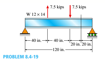
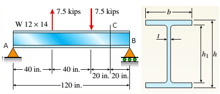
A W 12 X 14 wide-flange beam (see Table F-l(a), Appendix F) is simply supported with a span length of 120 in. (see figure). The beam supports two anti-symmetrically placed concentrated loads of 7,5 kips each.
At a cross section located 20 in. from the right-hand support, determine the principal stresses (7]and (7\ and the maximum shear stress Tmaw at each of the following locations: (a) the top of the beam, (b) the top of the web, and (c) the neutral axis,
(a).
To find: Values of principal stresses and maximum shear stress at top of beam.
Answer to Problem 8.4.19P
Values of principal stress :
Maximum shear stress
Explanation of Solution
Given Information:
Beam length
Point load
Dimensions of beam,
Concept Used:
Bending stress
Shear stress
Principal normal stresses
Maximum shear stress

From equilibrium:
So, bending moment at point
Shear force at point
Moment of inertia:
First moment of area at the top of beam shall be zero,
So, bending stress at top:
And shear stress at that point:
For this situation no stress in
Values of normal stress is given by following equation:
Maximum shear stress:
Conclusion:
Hence, we get:
Values of principal stress:
Maximum shear stress
(b).
To find: Values of principal stresses and maximum shear stress at top of web.
Answer to Problem 8.4.19P
Values of principal stress:
Maximum shear stress
Explanation of Solution
Given Information:
Beam length
Point load
Dimensions of beam,
Concept Used:
Bending stress
Shear stress
Principal normal stresses
Maximum shear stress

From equilibrium,
So, bending moment at point
Shear force at point
Moment of inertia:
First moment of area of flange:
So, bending stress at top of web:
And shear stress at that point:
For this situation no stress in
Principal normal stresses are given by following equation,
Maximum shear stress,
Conclusion:
Hence we get,
Principal stresses
Maximum shear stress
(c).
Find principal stresses and maximum shear stress at neutral axis.
Answer to Problem 8.4.19P
Principal stresses
Maximum shear stress
Explanation of Solution
Given Information:
Beam length
Point load
Dimensions of beam,
Concept Used:
Bending stress
Shear stress
Principal normal stresses
Maximum shear stress
From equilibrium,
So bending moment at point
Shear force at point
Moment of inertia,
First moment of area for the section above the neutral axis,
So bending stress at neutral axis,
And shear stress at that point,
For this situation no stress in
Principal normal stresses are given by following equation,
Maximum shear stress,
Conclusion:
Hence we get,
Principal stresses
Maximum shear stress
Want to see more full solutions like this?
Chapter 8 Solutions
Mechanics of Materials (MindTap Course List)


- A bimetallic beam used in a temperature-control switch consists of strips of aluminum and copper bonded together as shown in the figure, which is a cross-sectional view. The width of the beam is LO in,, and each strip has a thickness of 1/16 in. Under the action of a bending moment M = 12 lb-in, acting about the z axis, what are the maximum stresses aaand ecin the aluminum and copper, respectively? (Assume fA, = 10,5 x l0 psi and ecu= 16,8 × 10⁶ psi,)arrow_forwardA reinforced concrete slab (see figure) is reinforced with 13-mm bars spaced 160 mm apart at d = 105 mm from the top of the slab. The modulus of elasticity for the concrete is Ec= 25 GPa, while that of the steel is £s = 200 G Pa. Assume that allowable stresses for concrete and steel arecrac = 9.2 MPa and us = 135 MPa. l()5 mm Find the maximum permissible positive bending moment for a l-m wide strip of the slab. What is the required area of steel reinforcement, A^ if a balanced condition must be achieved? What is the allowable positive bending moment? (Recall that in a balanced design, both steel and concrete reach allowable stress values simultaneously under the design moment.)arrow_forwardA simple beam that is 18 ft long supports a uniform load of intensity q. The beam is constructed of two C8 x 11.5 sections (channel sections or C-shapes) on either side of a 4 × 8 (actual dimensions) wood beam (see the cross section shown in the figure part a). The modulus of elasticity of the steel (E; = 30,000 ksi) is 20 times that of the wood (Ew). (a) If the allowable stresses in the steel and wood are 12,000 psi and 900 psi, respectively, what is the allowable load qmax Note: Disregard the weight of the beam, and see Table F-3(a) of Appendix F for the dimensions and properties of the C-shape beam. (b) If the beam is rotated 90° to bend about its v axis (see figure part b) and uniform load q = 250 lb/ft is applied, find the maximum stresses trs and crw in the steel and wood, respectively Include the weight of the beam. (Assume weight densities of 35 lb/ft3 and 490 lb/ft3 for the wood and steel, respectively.)arrow_forward
- A cantilever beam(Z, = 6 ft) with a rectangular cross section (/> = 3.5 in., h = 12 in.) supports an upward load P = 35 kips at its free end. (a) Find the state of stress ((7T, o^., and r in ksi) on a plane-stress element at L/2 that is i/ = 8 in. up from the bottom of the beam. Find the principal normal stresses and maximum shear stress. Show these stresses on sketches of properly oriented elements. (b) Repeat part (a) if an axial compressive centroidal load N = 40 kips is added at Barrow_forwardA simple beam with a rectangular cross section (width, 3,5 inL; height, 12 in,) carries a trapczoi-dally distributed load of 1400 lb/ft at A and 1000 lb/ft at B on a span of 14 ft (sec figure). Find the principal stresses 2 and the maximum shear stress r__ at a cross section 2 ft from the left-hand support at each of the locations: (a) the neutral axis, (b) 2 in. above the neutral axis, and (c) the top of the beam. (Disregard the direct compressive stresses produced by the uniform load bearing against the top of the beam.)arrow_forwardA W 310 x 52 steel beam is subjected to a point load P = 45 kN and a transverse load V = 20 kN at B. The beam has length L =2m.(a) Calculate the principal normal stresses and the maximum shear stress on element D located on the web right below the top flange and near the fixed support. Neglect the weight of the beam, (b) Repeat Part a atcentroid C (sec figure). See Table F-l(b), Appendix F, for beam propertiesarrow_forward
- A beam with a wide-flange cross section (see figure) has the following dimensions: h = 120 mm, r = 10 mm, h = 300 mm, and /ij = 260 mm. The beam is simply supported with span length L = 3,0 im A concentrated load P = 120 kN acts at the midpoint of the span. At across section located 1.0 m from the left-hand support, determine the principal stresses tr, and tr2and the maximum shear stress Tmax at each of the following locations: (a) the top of the beam, (b) the top of the web, and (c) the neutral axisarrow_forwardA simple beam of span length 3.2 m carries a uniform load of intensity 48 kN/m, The cross section of the beam is a hollow box with wood flanges and steel side plates, as shown in the figure. The wood flanges are 75 mm x 100 mm in cross section, and the steel plates are 300 mm deep. What is the required thickness t of the steel plates if the allowable stresses are 120 M Pa for the steel and 6,5 M Pa for the wood? (Assume that the moduli of elasticity for the steel and wood are 210 GPa and 10 GPa, respectively, and disregard the weight of the beam.)arrow_forwardA W 12 x 50 steel wide-flange beam and a segment of a 4-inch thick concrete slab (see figure) jointly resist a positive bending moment of 95 kip-ft. The beam and slab are joined by shear connectors that are welded to the steel beam. (These connectors resist the horizontal shear at the contact surface.) The moduli of elasticity of the steel and the concrete are in the ratio 12 to 1. Determine the maximum stresses r1 and xtin the steel and concrete, respectively. Note: See Table F-l(a) of Appendix F for the dimensions and properties of the steel beam.arrow_forward
- A beam with a wide-flange cross section (see figure) has the following dimensions: b = 5 in., t = 0.5 in,, ft = 12 in., and /?, = 10.5 in. The beam is simply supported with span length L = 10 ft and supports a uniform load q = 6 kips/fL Calculate the principal stresses *rl and and the maximum shear stress t__ at a cross section located [|] JA 3 ft from the left-hand support at each of the following locations: (a) the bottom of the beam, (b) the bottom of the web, and (c) the neutral axisarrow_forwardA reinforced concrete T-beam (see figure) is acted on by a positive bending moment of M = 175 kip-ft. Steel reinforcement consists of four bars of 1.41-inch diameter. The modulus of elasticity for the concrete is Ec= 3000 ksi while that of the steel is £s = 29,000 ksi. Let b = 48 im, rf = 4 in., bw=15 in,, and d = 24 in, Find the maximum stresses in steel and concrete, If allowable stresses for concrete and steel are o"ac = 1400 psi and tr^ =18 ksi, respectively, what is the maximum permissible positive bending moment?arrow_forwardA W 12 x 35 steel cantilever beam is subjected to an axial load P = 10 kips and a transverse load V = 15 kips. The beam has length L = 6 ft, (a) Calculate the principal normal stresses and the maximum shear stress for an clement located at C near the fixed support. Neglect the weight of the beam, (b) Repeat Part a for point D which is 4 in. above point C (see figure). See Table F-l(a), Appendix F, for beam properties.arrow_forward
 Mechanics of Materials (MindTap Course List)Mechanical EngineeringISBN:9781337093347Author:Barry J. Goodno, James M. GerePublisher:Cengage Learning