
Steel Design (Activate Learning with these NEW titles from Engineering!)
6th Edition
ISBN: 9781337094740
Author: Segui, William T.
Publisher: Cengage Learning
expand_more
expand_more
format_list_bulleted
Concept explainers
Videos
Textbook Question
Chapter 8, Problem 8.4.19P
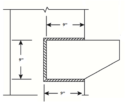
a. Use LRFD and design a welded connection for the bracket shown in Figure P8.4-19. All structural steel is A36. The horizontal 10-inch dimension is a maximum.
b. State why you think your weld size and configuration are best.
Expert Solution & Answer

Trending nowThis is a popular solution!

Students have asked these similar questions
a. Use LRFD and design a welded connection for the bracket shown in Figure . All structural steel is A36. The horizontal 10inch dimension is a maximum. b. State why you think your weld size and configuration are best.
Find the size of E70 fillet weld required for the shear and tension connection shown. Use the following details:
P = 250 kNe = 130 mmb = 150 mmd = 200 mmAssume the column and bracket plate does not control the strength.
Select a double-angle tension member and design a welded connection to resist a dead load of 12 kips and a live load of 36 kips. The member will be 16 feet long and will be connected to a 5/8-inch-thick gusset plate. Use A36 steel for both the tension member and the gusset plate. Show your results on a sketch, complete with dimensions.
Chapter 8 Solutions
Steel Design (Activate Learning with these NEW titles from Engineering!)
Ch. 8 - Prob. 8.2.1PCh. 8 - Prob. 8.2.2PCh. 8 - A plate is used as a bracket and is attached to a...Ch. 8 - Prob. 8.2.4PCh. 8 - Prob. 8.2.5PCh. 8 - Prob. 8.2.6PCh. 8 - Prob. 8.2.7PCh. 8 - Prob. 8.2.8PCh. 8 - Prob. 8.2.9PCh. 8 - Prob. 8.2.10P
Ch. 8 - Prob. 8.2.11PCh. 8 - Prob. 8.2.12PCh. 8 - Prob. 8.2.13PCh. 8 - Prob. 8.3.1PCh. 8 - Prob. 8.3.2PCh. 8 - Prob. 8.3.3PCh. 8 - Prob. 8.3.4PCh. 8 - Prob. 8.3.5PCh. 8 - Prob. 8.3.6PCh. 8 - Prob. 8.3.7PCh. 8 - Prob. 8.3.8PCh. 8 - Prob. 8.3.9PCh. 8 - Prob. 8.3.10PCh. 8 - Use an elastic analysis and determine the maximum...Ch. 8 - Use an elastic analysis and determine the maximum...Ch. 8 - Use an elastic analysis and determine the maximum...Ch. 8 - Prob. 8.4.4PCh. 8 - Prob. 8.4.5PCh. 8 - Prob. 8.4.6PCh. 8 - Use an elastic analysis and compute the extra load...Ch. 8 - Use an elastic analysis and compute the extra load...Ch. 8 - Prob. 8.4.9PCh. 8 - Prob. 8.4.10PCh. 8 - Prob. 8.4.11PCh. 8 - Prob. 8.4.12PCh. 8 - Prob. 8.4.13PCh. 8 - Prob. 8.4.14PCh. 8 - Prob. 8.4.15PCh. 8 - Prob. 8.4.16PCh. 8 - Prob. 8.4.17PCh. 8 - Prob. 8.4.18PCh. 8 - a. Use LRFD and design a welded connection for the...Ch. 8 - Prob. 8.4.20PCh. 8 - Prob. 8.5.1PCh. 8 - Prob. 8.5.2PCh. 8 - Prob. 8.5.3PCh. 8 - Prob. 8.5.4PCh. 8 - Prob. 8.5.5PCh. 8 - Prob. 8.6.1PCh. 8 - Prob. 8.6.2PCh. 8 - Prob. 8.6.3PCh. 8 - Prob. 8.6.4PCh. 8 - Prob. 8.7.1PCh. 8 - Prob. 8.7.2PCh. 8 - Prob. 8.7.3PCh. 8 - Prob. 8.8.1PCh. 8 - Prob. 8.8.2PCh. 8 - Prob. 8.8.3PCh. 8 - Prob. 8.8.4P
Knowledge Booster


Learn more about
Need a deep-dive on the concept behind this application? Look no further. Learn more about this topic, civil-engineering and related others by exploring similar questions and additional content below.Similar questions
- Determine the adequacy of the hanger connection in Figure P7.8-2 Account for prying action. a. Use LRFD. b. Use ASD.arrow_forwardSelect an American Standard Channel shape for the following tensile loads: dead load = 54 kips, live load = 80 kips, and wind load = 75 kips. The connection will be with longitudinal welds. Use an estimated shear lag factor of U = 0.85. (In a practical design, once the member was selected and the connection designed, the value of U would be computed and the member design could be revised if necessary.) The length is 17.5 ft. Use Fy=50 ksi and Fu=65 ksi. a. Use LRFD. b. Use ASD.arrow_forwardUse an elastic analysis and determine the maximum load per inch of weld.arrow_forward
- Use an elastic analysis and compute the extra load in the weld (in kips per inch of length) caused by the eccentricity.arrow_forwardUse load and resistance factor design and select a W shape with a nominal depth of 10 inches (a W 10) to resist a dead load of 175 kips and a live load of 175 kips. The connection will be through the flanges with two lines of 11 4 -inch-diameter bolts in each flange, as shown in Figure P3.6-6. Each line contains more than two bolts. The length of the member is 30 feet. Use A588 steal.arrow_forward
arrow_back_ios
arrow_forward_ios
Recommended textbooks for you
 Steel Design (Activate Learning with these NEW ti...Civil EngineeringISBN:9781337094740Author:Segui, William T.Publisher:Cengage Learning
Steel Design (Activate Learning with these NEW ti...
Civil Engineering
ISBN:9781337094740
Author:Segui, William T.
Publisher:Cengage Learning
Properties & Application Of Different Carbon Steels - Metals, Alloys, Cement & Refractory Materiall; Author: Ekeeda;https://www.youtube.com/watch?v=lwT0Bdd8bPE;License: Standard YouTube License, CC-BY