
Mechanics of Materials (MindTap Course List)
9th Edition
ISBN: 9781337093347
Author: Barry J. Goodno, James M. Gere
Publisher: Cengage Learning
expand_more
expand_more
format_list_bulleted
Videos
Textbook Question
Chapter 8, Problem 8.4.21P
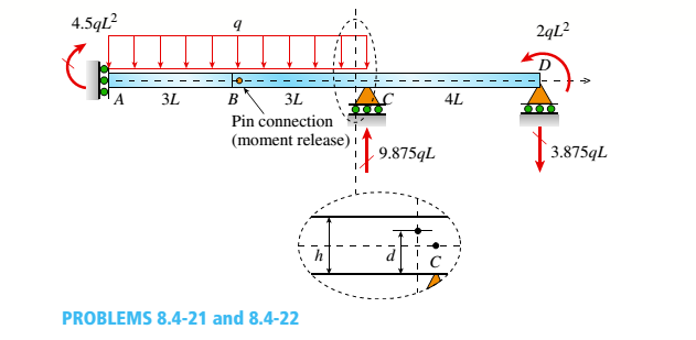
Beam A BCD has a sliding support at A, roller supports at C and A and a pin connection at B (see figure). Assume that the beam has a rectangular cross section (b = 4 in., h = 12 in.). Uniform load q acts on ABC and a concentrated moment is applied at D. Let load variable q = 1750 lb/ft, and assume that dimension variable L = 4 ft. First, use statics to confirm the reaction moment at A and the reaction forces at Cand A as given in the figure. Then find the ratio of the magnitudes of the principal stresses (crj/os) just left of support Cat a distance d = 8 in. up from the bottom,
Expert Solution & Answer

Trending nowThis is a popular solution!

Chapter 8 Solutions
Mechanics of Materials (MindTap Course List)
Ch. 8 - A spherical balloon is filled with a gas. The...Ch. 8 - A spherical balloon with an outer diameter of 500...Ch. 8 - A large spherical tank (see figure) contains gas...Ch. 8 - Solve the preceding problem if the internal...Ch. 8 - A hemispherical window (or viewport) in a...Ch. 8 - A rubber ball (sec figure) is inflated to a...Ch. 8 - (a) Solve part (a) of the preceding problem if the...Ch. 8 - A spherical steel pressure vessel (diameter 500...Ch. 8 - A spherical tank of diameter 48 in. and wall...Ch. 8 - Solve the preceding problem for the following...
Ch. 8 - A spherical stainless-steel tank having a diameter...Ch. 8 - Solve the preceding problem if the diameter is 480...Ch. 8 - : A hollow, pressurized sphere having a radius r =...Ch. 8 - A fire extinguisher tank is designed for an...Ch. 8 - Prob. 8.3.2PCh. 8 - A scuba t a n k (see fig ure) i s bci ng d e...Ch. 8 - A tall standpipc with an open top (see figure) has...Ch. 8 - An inflatable structure used by a traveling circus...Ch. 8 - A thin-walled cylindrical pressure vessel of a...Ch. 8 - A strain gage is installed in the longitudinal...Ch. 8 - A circular cylindrical steel tank (see figure)...Ch. 8 - A cylinder filled with oil is under pressure from...Ch. 8 - Solve the preceding problem if F =90 mm, F = 42...Ch. 8 - A standpipe in a water-supply system (see figure)...Ch. 8 - A cylindrical tank with hemispherical heads is...Ch. 8 - : A cylindrical tank with diameter d = 18 in, is...Ch. 8 - A pressurized steel tank is constructed with a...Ch. 8 - Solve the preceding problem for a welded Tank with...Ch. 8 - A wood beam with a cross section 4 x 6 in. is...Ch. 8 - Prob. 8.4.2PCh. 8 - A simply supported beam is subjected to two point...Ch. 8 - A cantilever beam with a width h = 100 mm and...Ch. 8 - A beam with a width h = 6 in. and depth h = 8 in....Ch. 8 - Beam ABC with an overhang BC is subjected to a...Ch. 8 - A cantilever beam(Z, = 6 ft) with a rectangular...Ch. 8 - Solve the preceding problem for the following...Ch. 8 - A simple beam with a rectangular cross section...Ch. 8 - An overhanging beam ABC has a guided support at A,...Ch. 8 - Solve the preceding problem if the stress and...Ch. 8 - A cantilever wood beam with a width b = 100 mm and...Ch. 8 - . A cantilever beam (width b = 3 in. and depth h =...Ch. 8 - A beam with a wide-flange cross section (see...Ch. 8 - A beam with a wide-flange cross section (see...Ch. 8 - A W 200 x 41.7 wide-flange beam (see Table F-l(b),...Ch. 8 - A W 12 x 35 steel beam is fixed at A. The beam has...Ch. 8 - A W 360 x 79 steel beam is fixed at A. The beam...Ch. 8 - A W 12 X 14 wide-flange beam (see Table F-l(a),...Ch. 8 - A cantilever beam with a T-section is loaded by an...Ch. 8 - Beam A BCD has a sliding support at A, roller...Ch. 8 - , Solve the preceding problem using the numerical...Ch. 8 - A W 12 x 35 steel cantilever beam is subjected to...Ch. 8 - A W 310 x 52 steel beam is subjected to a point...Ch. 8 - A solid circular bar is fixed at point A. The bar...Ch. 8 - A cantilever beam with a width h = 100 mm and...Ch. 8 - Solve the preceding problem using the following...Ch. 8 - A cylindrical tank subjected to internal...Ch. 8 - A cylindrical pressure vessel having a radius r =...Ch. 8 - A pressurized cylindrical tank with flat ends is...Ch. 8 - A cylindrical pressure vessel with flat ends is...Ch. 8 - The tensional pendulum shown in the figure...Ch. 8 - The hollow drill pipe for an oil well (sec figure)...Ch. 8 - Solve the preceding problem if the diameter is 480...Ch. 8 - . A segment of a generator shaft with a hollow...Ch. 8 - A post having a hollow, circular cross section...Ch. 8 - A sign is supported by a pole of hollow circular...Ch. 8 - A sign is supported by a pipe (see figure) having...Ch. 8 - A traffic light and signal pole is subjected to...Ch. 8 - Repeat the preceding problem but now find the...Ch. 8 - A bracket ABCD having a hollow circular cross...Ch. 8 - A gondola on a ski lift is supported by two bent...Ch. 8 - Beam A BCD has a sliding support at A, roller...Ch. 8 - A double-decker bicycle rack made up of square...Ch. 8 - A semicircular bar AB lying in a horizontal plane...Ch. 8 - Repeat Problem 8.5-22 but replace the square tube...Ch. 8 - An L-shaped bracket lying in a horizontal plane...Ch. 8 - A horizontal bracket ABC consists of two...Ch. 8 - , An arm A BC lying in a horizontal plane and...Ch. 8 - A crank arm consists of a solid segment of length...Ch. 8 - A moveable steel stand supports an automobile...Ch. 8 - A mountain bike rider going uphill applies a force...Ch. 8 - Determine the maximum tensile, compressive, and...Ch. 8 - Prob. 8.5.32PCh. 8 - A plumber's valve wrench is used to replace valves...Ch. 8 - A compound beam ABCD has a cable with force P...Ch. 8 - A steel hanger bracket ABCD has a solid, circular...
Knowledge Booster


Learn more about
Need a deep-dive on the concept behind this application? Look no further. Learn more about this topic, mechanical-engineering and related others by exploring similar questions and additional content below.Similar questions
- Frame ABCD carries two concentrated loads (2P at T and P at ZX see figure) and also a linearly varying distributed load on AB, Find expressions for shear force Fand moment A/at x = L/3 of beam AB in terms of peak load intensity q0, force P, and beam length variable L. Let q0= P/L.arrow_forwardA simple beam of span length 3.2 m carries a uniform load of intensity 48 kN/m, The cross section of the beam is a hollow box with wood flanges and steel side plates, as shown in the figure. The wood flanges are 75 mm x 100 mm in cross section, and the steel plates are 300 mm deep. What is the required thickness t of the steel plates if the allowable stresses are 120 M Pa for the steel and 6,5 M Pa for the wood? (Assume that the moduli of elasticity for the steel and wood are 210 GPa and 10 GPa, respectively, and disregard the weight of the beam.)arrow_forwardBeam A BCD has a sliding support at A, roller supports at C and A and a pin connection at B (see figure). Assume that the beam has a rectangular cross section (b = 4 in., h = 12 in.). Uniform load q acts on ABC and a concentrated moment is applied at D. Let load variable q = 1750 lb/ft, and assume that dimension variable L = 4 ft. First, use statics to confirm the reaction moment at A and the reaction forces at C and A as given in the figure. Then find the ratio of the magnitudes of the principal stresses (crj/os) just left of support Cat a distance d = 8 in. up from the bottom, The pedal and crank are in a horizontal plane and points A and B are located on the top of the crank. The load P = 160 lb acts in the vertical direction and the distances (in the horizontal plane) between the line of action of the load and points A and B are b\ = 5.0 in., h-, = 2.5 in., and/>3 = 1.0 in. Assume that the crank has a solid circular cross section with diameter d = 0.6 inarrow_forward
- A reinforced concrete T-beam (see figure) is acted on by a positive bending moment of M = 175 kip-ft. Steel reinforcement consists of four bars of 1.41-inch diameter. The modulus of elasticity for the concrete is Ec= 3000 ksi while that of the steel is £s = 29,000 ksi. Let b = 48 im, rf = 4 in., bw=15 in,, and d = 24 in, Find the maximum stresses in steel and concrete, If allowable stresses for concrete and steel are o"ac = 1400 psi and tr^ =18 ksi, respectively, what is the maximum permissible positive bending moment?arrow_forwardA beam with a guided support and 10-ft span supports a distributed load of intensity q = 660 lb/ft over its first half (see figure part a) and a moment Mq = 300 ft-lb at joint B. The beam consists of a wood member (nominal dimensions 6 in. x 12 in. and actual dimensions 5.5 in. x 11.5 in. in cross section, as shown in the figure part b) that is reinforced by 0.25-in.-thick steel plates on top and bottom. The moduli of elasticity for the steel and wood are £s = 30 X 106 psi and £"w = 1.5 X 10⁶ psi, respectively. Calculate the maximum bending stresses trs in the steel plates and rw in the wood member due to the applied loads. If the allowable bending stress in the steel plates is = 14,000 psi and that in the wood is (T.dV!= 900 psi, find qmiiX. (Assume that the moment at .fi, A/0, remains at 300 ft-lb.) If q = 660 lb/ft and allowable stress values in part (b) apply, what is Müm^ at B?arrow_forwardSolve the preceding problem for a cantilever beam with data as b = 4 in., h = 9 in., L = 10 ft, P = 325 lb, and x = 45°.arrow_forward
- A wood beam 8 in. wide and 12 in. deep (nominal dimensions) is reinforced on top and bottom by 0,25-in.-thick steel plates (see figure part a), (a) Find the allowable bending moment A/max about the z axis if the allowable stress in the wood is 1100 psi and in the steel is 15,000 psi, (Assume that the ratio of the moduli of elasticity of steel and wood is 20.) (b) Compare the moment capacity of the beam in part a with that shown in the figure part b which has two 4 in. × 12 in, joists (nominal dimensions) attached to a 1/4 in, × 11.0 in, steel plate.arrow_forwardA simple beam that is 18 ft long supports a uniform load of intensity q. The beam is constructed of two C8 x 11.5 sections (channel sections or C-shapes) on either side of a 4 × 8 (actual dimensions) wood beam (see the cross section shown in the figure part a). The modulus of elasticity of the steel (E; = 30,000 ksi) is 20 times that of the wood (Ew). (a) If the allowable stresses in the steel and wood are 12,000 psi and 900 psi, respectively, what is the allowable load qmax Note: Disregard the weight of the beam, and see Table F-3(a) of Appendix F for the dimensions and properties of the C-shape beam. (b) If the beam is rotated 90° to bend about its v axis (see figure part b) and uniform load q = 250 lb/ft is applied, find the maximum stresses trs and crw in the steel and wood, respectively Include the weight of the beam. (Assume weight densities of 35 lb/ft3 and 490 lb/ft3 for the wood and steel, respectively.)arrow_forwardBeam ABC is fixed at support A and rests (at point B) upon the midpoint of beam DE (see part a of the figure). Thus, beam, ABC may be represented as a propped cantilever beam with an overhang BC and a linearly elastic support of stiffness k at point B (see part b of the figure). The distance from A to B is L = 10 ft, the distance from B to C is L/2 = 5 ft, and the length of beam DE is L = 10 ft. Both beams have the same flexural rigidity EI. A concentrated load P = 1700 lb acts at t lie free end of beam ABC. Determine the reactions RA, RB+ and MAfor beam ABC. Also, draw the shear-force and bending-moment diagrams for beam ABC, labeling all critical ordinates.arrow_forward
- The cantilever beam AB shown in the figure is an S6 × 12.5 steel I-beam with E = 30 × 106 psi. The simple beam DE is a wood beam 4 in. x 12 in. (nominal dimensions) in cross section with E = 1.5 x 10⁶ psi. A steel rod AC of diameter 0.25 in., length 10 ft, and E = 30 x 106 psi serves as a hanger joining the two beams. The hanger fits snugly between the beams before the uniform load is applied to beam DE. Determine the tensile force Fin the hanger and the maximum bending moments MABand MDEin the two beams due to the uniform load, which has an intensity q = 400 lb/ft. Hint: To aid in obtaining the maximum bending moment in beam DE, draw the shear-force and bending-moment diagrams.arrow_forwardFind support reactions at A and D and then calculate the axial force N. shear force 1 and bending moment 11 at mid-span of column BD. Let L = 4 m, q0 = 160N/m, P = 200N, and M0= 380 N .m.arrow_forwardA foot bridge on a hiking trail is constructed using two timber logs each having a diameter d = 0.5 m (see figure a). The bridge is simply supported and has a length L = 4 m. The top of each log is trimmed to form the walking surface (see Fig, b)LA simplified model of the bridge is shown in Fig. g. Each log must carry its own weight w = 1.2 kN/m and the weight (P = 850 N) of a person at mid-span, (see Fig. b). Determine the maximum tensile and compressive stresses in the beam (Fig, b) due to bending. If load h is unchanged, find the maximum permissible value of load ... if the allowable normal stress in tension and compression is 2.5 M Pa.arrow_forward
arrow_back_ios
SEE MORE QUESTIONS
arrow_forward_ios
Recommended textbooks for you
 Mechanics of Materials (MindTap Course List)Mechanical EngineeringISBN:9781337093347Author:Barry J. Goodno, James M. GerePublisher:Cengage Learning
Mechanics of Materials (MindTap Course List)
Mechanical Engineering
ISBN:9781337093347
Author:Barry J. Goodno, James M. Gere
Publisher:Cengage Learning
Mechanics of Materials Lecture: Beam Design; Author: UWMC Engineering;https://www.youtube.com/watch?v=-wVs5pvQPm4;License: Standard Youtube License