
Videos
Consider the class−AB output stage in Figure P8.48. The parameters are:
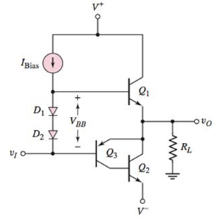
Figure P8.48
(a)
The value of
Answer to Problem 8.48P
Thevalue of the voltage
Explanation of Solution
Calculation:
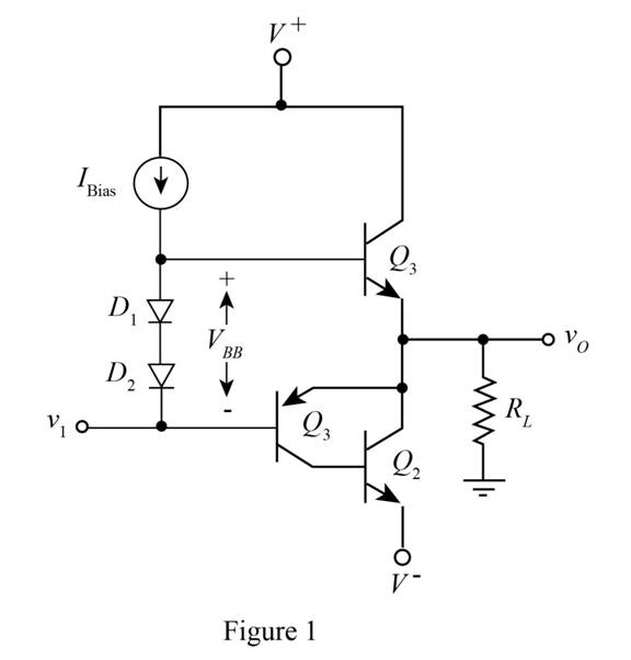
The given diagram is shown in Figure 1
The conversion from
The conversion from
The expression for the value of
Substitute
The expression for the value of the current
The expression for the value of the current
The expression for the value of the current
Substitute
The expression for the value of the current
The expression for the value of the current
The expression for the value of base to emitter voltage
The expression for the value of base to emitter voltage
The expression for the value of
Substitute
Substitute
Substitute
The expression for the value of base to emitter voltage
The expression for the value of base to emitter voltage
The expression for the value of the base to emitter voltage
Substitute
Substitute
Substitute
Substitute
The expression for the value of the current
Substitute
Substitute
Substitute
Substitute
The expression for the value of the voltage
Substitute
Conclusion:
Therefore, the value of the voltage
(b)
The value of
Answer to Problem 8.48P
The value of power delivered
Explanation of Solution
Calculation:
The expression for the value of the current
Substitute
The expression for the voltage
Substitute
The expression for the voltage
Substitute
The expression for the value of the voltage is given by,
Substitute
The expression for the value of the current for
Substitute
The expression for the value of the power delivered to the load is given by,
Substitute
The expression for the power delivered in the transistor of
Substitute
The expression for the power delivered in the transistor of
Substitute
The expression for the value of the current
Substitute
The expression for the value of the power dissipated in the transistor
Substitute
Conclusion:
Therefore, the value of power delivered
Want to see more full solutions like this?
Chapter 8 Solutions
Microelectronics: Circuit Analysis and Design


- Given the differential amplifier circuit below. Determine the following: emitter current, differential mode voltage gain, common mode voltage gain and CMRR.arrow_forwardDetermine the ICQ and VCEQ of the circuit. Assume ßDC = 85. Then plot the DCLL and Q-point of the circuitarrow_forwardDesign a Single-Stage Common Emitter Class A Amplifier Specifications:Voltage Divider Bias Circuit Supply: Any value from 10Vdc to 24VdcLoad: 1kΩVoltage Gain: Any value from 80 to 400Lower Cutoff Frequency: 100 HzSinusoidal source (zero internal resistance): 50mVp-pTransistor: Si, β = 75 • Base-Collector capacitance = 8pF • Base-Emitter Capacitance = 25pF a) compute for the biasing resistances.b) determine the dc transistor terminal voltages and transistor currents.arrow_forward
- The topic is about BJT DC Analysis. Please show the correct and complete solution to this problem. Thank you!arrow_forwardDraw the circuit diagram of a resistance–capacitance coupled source followerarrow_forwardDescribe the combined effect of the RC circuits for higher frequency response in a BJT & FETamplifier. the subject : Analogue Electronics IIarrow_forward
- A) What does VCO stand four? Show by drawing the relationship between its input and output signals. Compare VCO circuit with LC Tank circuit in terms of circuit functionality and how the output is generated in each of them. B) Compare between AM and FM in terms of noise immunity, interference, equipment complexity and cost and line of site transmission.arrow_forward(a) A current source with Rout = βoro is used to bias a standard bipolar differential amplifier. What is an expression for the CMRR of this amplifier for single-ended outputs?arrow_forward(b)A pulse of amplitide V is applied to vIN at time t=0 seconds for ΔT seconds. Find an expression for the time t1 at which the MOSFET M2 turns off in terms of the circuit and MOSFET parameters, assuming t1< ΔT.arrow_forward
- Draw the Nyquist plot for the system in the figure below. Using the Nyquist stability criterion, determine the range of K for which the system is stable. Consider both positive and negative values of K.( Need only handwritten solution please otherwise downvote)arrow_forwardDescribe cmrr with the figure.arrow_forwardCircuit analysis questionarrow_forward
 Introductory Circuit Analysis (13th Edition)Electrical EngineeringISBN:9780133923605Author:Robert L. BoylestadPublisher:PEARSON
 Delmar's Standard Textbook Of ElectricityElectrical EngineeringISBN:9781337900348Author:Stephen L. HermanPublisher:Cengage Learning
 Programmable Logic ControllersElectrical EngineeringISBN:9780073373843Author:Frank D. PetruzellaPublisher:McGraw-Hill Education
 Fundamentals of Electric CircuitsElectrical EngineeringISBN:9780078028229Author:Charles K Alexander, Matthew SadikuPublisher:McGraw-Hill Education
 Electric Circuits. (11th Edition)Electrical EngineeringISBN:9780134746968Author:James W. Nilsson, Susan RiedelPublisher:PEARSON
 Engineering ElectromagneticsElectrical EngineeringISBN:9780078028151Author:Hayt, William H. (william Hart), Jr, BUCK, John A.Publisher:Mcgraw-hill Education,