
(a)
The design of a four-bolt unstiffened end-plate connection for a
Answer to Problem 8.8.4P
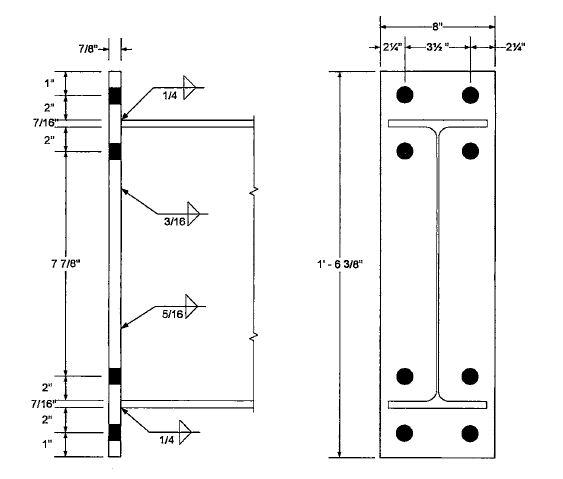
¼-in. fillet weld at each flange.
3/16-in. fillet weld on each side of the web in the tension region
5/16-in. fillet weld on each side of the web between mid-depth and the compression flange.
Explanation of Solution
Given:
Dead load = 13 kips
Live load = 34 kips
Dead load moment = 20 ft-kips
Live load moment = 48 ft-kips
A992 steel for the structural shapes
A36 steel for the end plate
Group A pretensioned bolts
Formula used:
Calculation:
Determine the factored shear and moment:
From the dimensions and properties tables
Workable gauge = 3.50 in.
For the bolt pitch, try
For the gauge distance, use the workable gauge g = 3.50 in.
Required bolt diameter:
Try
Moment strength based on bolt strength:
Determine end-plate width:
Minimum
The minimum plate width is
Maximum effective end-plate width =
Try
Determine the required plate thickness:
Therefore, use the original value of
Required
Try
Beam flange force:
The shear yield strength of the end plate is
Shear rupture strength of end plate:
Check bolt shear:
The compression side bolts must be capable of resisting the entire vertical shear.
For 4 bolts,
Check bearing in the plate at the compression side bolts.
For the outer bolts,
The upper limit is
Therefore, use
Since the inner bolts are not near an edge or adjacent bolts, the outer bolts control. Shear controls overall.
Check bearing in the column flange:
Use
The upper limit is
Therefore, use
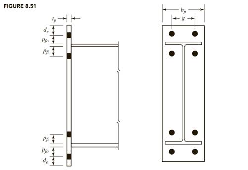
The plate length, using detailing dimensions and the notation of figure given below from the textbook, is

Use a
Beam flange to plate weld design:
The flange force is
AISC Design Guide 4 recommends that the minimum design flange force should be 60% of the flange yield strength:
Minimum
Therefore, use the actual flange force of 102 kips.
The flange weld length is
The weld strength is
Where, D is the weld size in sixteenths of an inch and the factor of 1.5 accounts for the direction of the load on the weld. If we equate the weld strength to the flange force,
From AISC Table J2.4, the minimum weld size is 3/16-in. (based on the thickness of the flange, which is the thinner connected part).
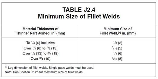
Use a ¼-in. fillet weld at each flange.
Beam web to plate weld design:
To develop the yield stress in the web near the tension bolts, let
Minimum size = 3/16 in. based on web thickness.
Use a 3/16-in. fillet weld on each side of the web in the tension region.
The applied shear of
- From the mid-depth to the compression flange.
- From the inner row of tension bolts plus
Use
Equating the weld strength to the required shear strengths, we get
Use a 5/16-in. fillet weld on each side of the web between mid-depth and the compression flange.
The design is summarized in the figure below:

Conclusion:
Use a
(b)
The design of a four-bolt unstiffened end-plate connection for a
Answer to Problem 8.8.4P
¼-in. fillet weld at each flange.
3/16-in. fillet weld on each side of the web in the tension region
5/16-in. fillet weld on each side of the web between mid-depth and the compression flange.
Explanation of Solution
Given:
Dead load = 13 kips
Live load = 34 kips
Dead load moment = 20 ft-kips
Live load moment = 48 ft-kips
A992 steel for the structural shapes
A36 steel for the end plate
Group A pretensioned bolts
Formula used:
Calculation:
Determine the factored shear and moment:
From the dimensions and properties tables,
Workable gauge = 3.50 in.
For the bolt pitch, try
For the gauge distance, use the workable gauge g = 3.50 in.
Required bolt diameter:
Try
Moment strength based on bolt strength:
Determine end-plate width:
Minimum
The minimum plate width is
Maximum effective end-plate width =
Try
Determine the required plate thickness:
Therefore, use the original value of
Required
Try
Beam flange force:
The shear yield strength of the end plate is
Shear rupture strength of end plate:
Check bolt shear:
The compression side bolts must be capable of resisting the entire vertical shear.
For 4 bolts,
Check bearing in the plate at the compression side bolts.
For the outer bolts,
The upper limit is
Therefore, use
Since the inner bolts are not near an edge or adjacent bolts, the outer bolts control. Shear controls overall.
Check bearing in the column flange:
Use
The upper limit is
Therefore, use
The plate length, using detailing dimensions and the notation of figure given below from the textbook, is
Use a
Beam flange to plate weld design:
The flange force is
AISC Design Guide 4 recommends that the minimum design flange force should be 60% of the flange yield strength:
Minimum
Therefore, use the minimum flange force of 86.06 kips.
The flange weld length is
The weld strength is
where D is the weld size in sixteenths of an inch and the factor of 1.5 accounts for the direction of the load on the weld. If we equate the weld strength to the flange force,
From AISC Table J2.4, the minimum weld size is 3/16-in. (based on the thickness of the flange, which is the thinner connected part).
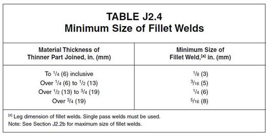
Use a ¼-in. fillet weld at each flange.
Beam web to plate weld design:
To develop the yield stress in the web near the tension bolts, let
Minimum size = 3/16 in. based on web thickness.
Use a 3/16-in. fillet weld on each side of the web in the tension region.
The applied shear of
- From the mid-depth to the compression flange.
- From the inner row of tension bolts plus
Use
Equating the weld strength to the required shear strengths, we get
Use a 5/16-in. fillet weld on each side of the web between mid-depth and the compression flange.
The design is summarized in the figure below:
Conclusion:
Use a
Want to see more full solutions like this?
Chapter 8 Solutions
Steel Design (Activate Learning with these NEW titles from Engineering!)

- Design the spacing of the main bars and temperature bars of a one-way slabhaving a total span of 5 m. The slab is supported with hinge in the left support anda vertical cable located 1.5 m from the right support. The distance between thecables of the slab is 2.3 m. The slab is to carry a live load pressure of 2.4 kPa anda dead load pressure (including self-weight) of 4 kPa. Assume f’c = 27.6 MPa andfy = 276 MPa for main and temperature bars. Use 12 mm ∅ for main bars and 10mm ∅ for temperature bars. The slab is not exposed to earth or weather. Usethickness of slab of 120 mm. Use NSCP 2001.arrow_forwardSimply Supported Beam ABCDE below carries multiple loads as shown. A built-upsection made from a T-Section and a Channel (C-Section) fastened together by 16mm∅ bolts,equally spaced from the center of the section, with shearing capacity τ=100 MPa, for bearing σb= 220 MPa for rivets in single shear and σb = 280 MPa for rivets in double shear. E=200GPa forall materials. 1. Determine the maximum positive bending moment in the beam in kN-m.2. Determine the maximum shear in kN.3. Determine the location of Neutral Axis, in mm, from the top of the section.arrow_forwardThe bracket BCD is hinged at € and attached to a control cable | ! at B. For the loading shown, determine (a) the tension in the cable, (b) the reaction at C. a=0. 18m 20N 20N 8 c o I_.l_nm—l—um—-l 02¢marrow_forward
- Design a framed beam connection for a W18 x 50 to support a dead load reaction of 30 k and a live load reaction of 20 k, using the LRFD and ASD methods.The beam’s top flange is to be coped for a 2-in depth, and 7/8-in A325-X bolts in standard-size holes are to be used.The beam is connected to a W27 x 146 girder. Connection is A36,while W shapes are A992arrow_forwardA W section steel purlin span 6.7 m between roof trusses on centers. The roof is assumed to support a dead load of 880 N/m2 of roof surface including self-weight and a live load of 816 N/m2 of horizontal roof surface projection. The slope of the roof truss is 1 vertical to 2 horizontal and the purlins are spaced 1 m on centers. Use A36 with Fy = 248 MPa. Assume all loads pass through the center of gravity of the section. Sag rods are to be placed at the middle thirds between trusses. Determine the ratio of the actual to the allowable bending stress. DO NOT ROUND-OFF DURING THE COURSE OF SOLVING. ANSWER IN FOUR DECIMAL PLACES. Properties of W Section A = 2,887 mm2 d = 192.5 mm bf = 100.7 mm tf = 10.82 mm Sx = 174,900 mm3 Sy = 36,133 mm3 tw = 6.1 mm Use the following allowable stresses (NSCP 2001): For bending about strong axis, Fbx=0.66 Fy For bending about weak axis, Fby=0.75Fyarrow_forwardA T-beam (internal) for a floor system has a slab thickness of 100mm and a total depth of 550mm. It hasa web thickness of 300mm. The T-beam is casted monolithically with the slab. The beam has a simple spanof 6.0m with a spacing of 2.4m center to center. The beam carries a live load moment of 163 kN.m and adead load moment of 84 kN.m. Assume f’c = 20.7 MPa and fy = 413.7 MPa. Assume steel covering to thecentroid of the reinforcement is 65mm. Determine the following and discuss your solution:(a) Effective width of flange(b) Depth of compression block(c) Steel area requiredarrow_forward
- Simply Supported Beam ABCDE below carries multiple loads as shown. A built-upsection made from a T-Section and a Channel (C-Section) fastened together by 16mm∅ bolts,equally spaced from the center of the section, with shearing capacity τ=100 MPa, for bearing σb= 220 MPa for rivets in single shear and σb = 280 MPa for rivets in double shear. E=200GPa forall materials. Determine the maximum positive bending moment in the beam in kN-m.arrow_forwardA short rectangular column 300 mm on one side and 400 mm on the other side. It is reinforced with 8-20-mm-diameter (28) longhitudinal bars equally distributed to the shorte sides of the column. Use f'c = 21 MPa and fy = 415 MPa. Calculate the required spacing of 10-mm-diameter ties, s (mm). Calculate the nominal axial strength of the column, Pn (kN). Calculate the maximum ultimate axial load the column can carry, Pu (kN)arrow_forwardThe following frame has pin connections at A and B. If F1 = 60lbs, F2 = 45 lbs, a = 4.3 ft., b = 3.0 ft., c = 4.9 ft., and has atriangular distributed load with a max loading of wpeak = 14 lb/ft,Determine the connection forces at C acting on member BCD .arrow_forward
- A W14X120 is used as a tension member in atruss. The flanges of the member are connected to a gusset plate by ¾ inch boltas shown below. Use A36 steel with Fy=36 ksi and Fu=58 ksi Determine the Yielding Capacity of the section based on LRFD (kips)arrow_forwardDetermine the required length of cord AC shown so that the 8-kglamp can be suspended in the position shown. The undeformed lengthof spring AB is l'AB = 0.4 m, and the spring has a stiffness of kAB = 300 N/m.arrow_forwardA W12 x 79 of A572 Grade 60 steel is used as a compression member. It is 28 feet long, pinned at each end, and has additional support in the weak direction at a point 12 feet from the top. Can this member resist a service dead load of 180 kips and a service live load of 320 kips? a. Use LRFD. b. Use ASD.arrow_forward
 Steel Design (Activate Learning with these NEW ti...Civil EngineeringISBN:9781337094740Author:Segui, William T.Publisher:Cengage Learning