
Concept explainers
Videos
The resistance of loop 2 is greater than that loop l. (The loop are made from different materials.)
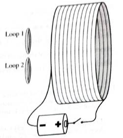
1. Is there a current induced through the wire of either of the loops:
• before the switch is closed? Explain.
• just after the switch is closed? Explain.
• a long after the switch is closed? Explain.
2. For the period of time that there is a current included through the wire of the loops, find the direction of the current.
3. The ratio of the induced currents for the two loops is found by experiment to be equal to the inverse of the ratio of the resistances of the loops.
What does this observation imply about the ratio of the induced emf in loop 1 to the induced emf in loop 2?
(1)
To Identify:
Induced current through wire of the loops as per the given conditions:
- Before the switch is closed.
- After when the switch is closed.
- After a long-time when the switch is closed.
Explanation of Solution
Introduction:
According to Faradays’ law, an e.m.f is induced in a loop of wire if there is a rate of change in flux passing through the wire.
Where,
Case1: Before the switch is closed:
Before the switch is closed, there is no current flowing in solenoid (bigger loop) that can produce changing magnetic field. Hence, there is no change in flux in the small loops. Therefore, there is no induced current in small coils.
Case 2: After the switch gets closed:
Just after the switch is closed, the current in the solenoid (bigger loop) goes from zero to maximum which makes the magnetic field lines passing through the small loops change. Hence, due to change in flux, there will be induced current in them. The loop with higher resistance will be associated with less induced current.
Case 3: After longtimewhen the switch isclosed:
After long time the switch is closed, there is constant current in solenoid (bigger loop) that produces constant magnetic field. Hence, there is no change in flux in the small loops. Therefore, there is no current in small loops.
Conclusion:
Therefore, following Faraday’s law, there is an induced current in small coils just when switch is closed and is zero for other cases.
(2)
To Find
The direction current induced through a wire of the loops.
Explanation of Solution
Introduction:
According to Lenz’s law, the induced emf will form a magnetic field which counteracts the change in flux.
By seeing the sign of the battery (current flows from positive to negative terminal) and using the right-hand rule, the direction of magnetic field induced in the greater loop must be from left to right. When switch is closed, then the induced current in small loop is in such a way that decreases the magnetic flux produced by the larger loop, hence, the induced current is in clockwise while seeing the loop from right. When switch is opened, the induced current will flow in anticlockwise direction.
Conclusion:
Therefore, the current induced through a wire of the loop will be such that it will oppose the change in flux produced by the bigger loop.
(3)
To Explain:
The ratio of induced emf in the loop 1to the loop 2.
Answer to Problem 1aT
Ratio of emf induced in loop 1to loop 2 is equal.
Explanation of Solution
Introduction:
According to Faradays’ law, an e.m.f is induced in a loop of wire if there is a rate of change in flux passing through the wire.
Where,
The induced emf depends on the rate of change in flux. Considering the area of the small loops same, the change in magnetic flux will be same for both the loops. Therefore, the induced emf will be same.
The induced current will be different in both the loops though, as the resistance of the loop 2 is greater than the loop 1.
Conclusion:
Therefore, induced emf will be same in both smaller loops.
Want to see more full solutions like this?
Chapter 8 Solutions
Tutorials in Introductory Physics
Additional Science Textbook Solutions
College Physics (10th Edition)
Physics for Scientists and Engineers: A Strategic Approach, Vol. 1 (Chs 1-21) (4th Edition)
Physics for Scientists and Engineers with Modern Physics
University Physics Volume 2
University Physics (14th Edition)
Essential University Physics (3rd Edition)


- Imagine moving along the axis of the current-carrying loop given above, starting at a point well to the left of the loop and ending at a point well to the right of the loop. (a) How would the magnetic field strength vary as you moved along this path? (I) it would be the same at all points along the path (ii) it would increase then decrease (iii) it would decrease then increase (b) Would the magnetic field direction vary as you moved along the path? Yes or no?arrow_forward1. Which would you choose--iron or steel-- for the following? Explain. a.) a bar magnetb.) the core of a transformerc.) the needle of a plotting compass 2. How would you use a magnet to distinguish a can made of iron from a can made of aluminum? 3. Without using another magnet, how would you know which end of the bar magnet is north pole and which is the south pole? 4. If the driver shaft of a generator is turned more rapidly, what will happen to the voltage?arrow_forward1. What is the direction of the magnetic fields produced by the electromagnet? Is it from positive to negative terminal or from negative to positive terminal? 2. After disconnecting the switch (OFF), removing the battery and copper wire from the nail. Did the nail still attract the pins? (Explain) 3. If you increase the number of turns of the coil, Does the strength of the electromagnet increases?arrow_forward
- 1.How does the looped conductor with the current I behave in the field B? Explain your answer. Note: The diagram shows the direction of a conventional current.arrow_forwardFigure 3 shows a straight wire carrying a current in upwarddirection. The wire is placed near a wire loop. For each case described below, answer the following questions:a. What is the direction of the magnetic flux through theloop?b. Is the magnitude of the flux through the loop increasing ordecreasing with time?c. What is the direction of the magnetic field produced by theinduced current in the loop?d. What is the direction of the current induced in the loop?1. Case 1: The current is increasing.2. Case 2: The current is decreasing.3. Case 3: The current is constant but the loop is being pulledaway from the straight wire.arrow_forwardThe circular conducting loops shown in the accompanying figure are parallel, perpendicular to the plane of the page, and coaxial. (a) When the switch S isclosed, what is the direction of the current induced in D? (b) When the switch is opened, what is the direction of the current induced in loop D?arrow_forward
- Indicate the direction of the induced current in each loop by writing clockwise, counterclockwise, or none for each of the 2 pictures. Please also explain the steps you used to get there/the physics behind why/how you got to the answer to help me better understand. Thank you soo much.arrow_forwardHere is a long solenoid (coils of wire along a long cylinder) and an end view of the solenoid. Conventional current runs counterclockwise in the solenoid and is increasing with time. Choose from the following possible directions (shown in figure 2) to answer the following questions: what is the direction (a – h) of the electric field at location 1 (marked with X)? and what is the direction (a – h) of the electric field at location 2 (marked with X)?arrow_forwardA square loop (each side is 10 cm) of wire with Resistance 100Ω is moved at a constant speed of 30cm/s across a uniform magnetic field 2 T, confined in a square region (Each side of the square is 20cm). (a) Graph the force needed to move the loop at a constant speed from -20 cm to 20cm (as shown in the figure). What will be the maximum force required? Assume that the force pointing to the right as positive (b) Graph the current induced in the loop as a function of distance from -20cm to 20cm. Assume clockwise current to be positive. What will be the maximum value of current? Hint: The figure is drawn not to scalearrow_forward
- A bar magnet is pulled away from the coil as shown in Figure 1.(a) Determine the direction of the induced current through R.(b) Explain your answer in (a).(c) Which point (P or Q) is at a higher potential?arrow_forwarda) What would happen to the magnetic field and the current if the direction of motion of the magnet is reversed? b) What would happen to the magnetic field and the current if the magnet is moved more quickly in the same direction? c) What would happen to the magnetic field and the current if the magnet is moved rapidly back and forth? My Answer: I attached my answer below as well as the drawing of the coil and magnet. I am just unsure as to whether my first to answers (a and b) are correct and then for c), what the affect on the magnetic field is. a) Current: If the direction of motion of the magnet was reversed then the direction of the current would also be reversed. Magnetic Field: Since the magnetic field in the coil wants to oppose the moving magnetic field, an induced magnetic field will be created that will attract the magnet and prevent it from moving away from the coil. b) Magnetic Field and Current: If the magnet moved more quickly in the same direction, then the…arrow_forwardThe loop in the figure below is rotated out of the plane of the drawing while B is kept constant. You can assume the rotation axis is along the horizontal direction in the figure. a) Does the magnitude of the flux through the loop increase or decrease with time? (Assume the loop has not had time to rotate by more than 90°.) Increase/Decrease? b) If the loop has only rotated a small amount, will the induced current be clockwise or counterclockwise?arrow_forward
 Physics for Scientists and Engineers: Foundations...PhysicsISBN:9781133939146Author:Katz, Debora M.Publisher:Cengage Learning