
Concept explainers
Videos
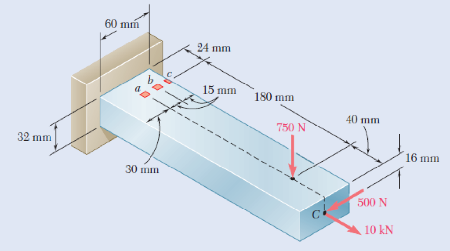
Three forces are applied to the bar shown. Determine the normal and shearing stresses at (a) point a, (b) point b, (c) point c.
Fig. P8.47
(a)
The normal and shearing stress at point a.
Answer to Problem 47P
The normal stress at point a is
The shear stress at point a is
Explanation of Solution
Given information:
The centric force p is
Calculation:
At point A:
Find the area of cross section
Here, b is the width of the bar and h is the height of the bar.
Substitute
Find the moment of inertia
Substitute
Find the moment of inertia
Substitute
Sketch the side view of bar as shown in Figure 1.
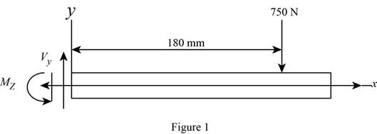
At the section containing point a, b, and c.
Refer to Figure 1.
Find the moment about z axis as follows:
Sketch the side view of bar as shown in Figure 2.
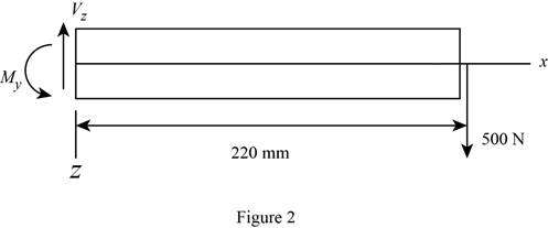
Find the moment about y axis as follows:
Find the normal stress
Here, P is the centric force, A is the area of rectangular cross section,
Substitute
Thus, the normal stress at point a is
Sketch the cross section at point a as shown in figure 3.
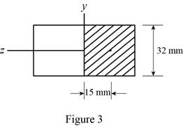
Determine the first moment area (Q) as follows:
Here,
Refer to Figure 2.
Substitute
Find the shear stress
Here,
Substitute
Thus, the shear stress at point a is
(b)
The normal and shearing stresses at point b.
Answer to Problem 47P
The normal stress at point b is
The shear stress at point b is
Explanation of Solution
Calculation:
At point b:
Find the normal stress
Substitute
Thus, the normal stress at point b is
Sketch the cross section at point b as shown in figure 4.
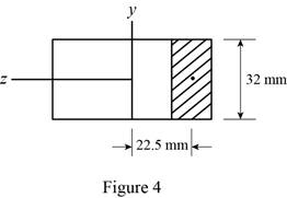
Determine the first moment area (Q) as follows:
Here,
Refer to Figure 2.
Substitute
Find the shear stress
Here,
Substitute
Thus, the shear stress at point b is
(c)
The normal and shearing stresses at point c.
Answer to Problem 47P
The normal stress at point c is
The shear stress at point c is
Explanation of Solution
Calculation:
Find the normal stress
Substitute
Thus, the normal stress at point c is
Find the shear stress
The point c is edge on the cross section. Since Q is zero.
Substitute
Thus, the shear stress at point c is
Want to see more full solutions like this?
Chapter 8 Solutions
Mechanics of Materials, 7th Edition


- A spherical gas container made of steel has a 20-ft outer diameter and a wall thickness of 7/16 in. Knowing that the internal pressure is 75 psi, determine the maximum normal stress and the maximum shearing stress in the container.arrow_forwardShow that the angle between the plane of the major principal stress and the plane of the maximum shear stress is 45° for any state of stress.arrow_forwardThe driveshaft of an automobile is being designed to transmit 238 hp at 3790 rpm. Determine the minimum diameter d required for a solid steel shaft if the allowable shear stress in the shaft is not to exceed 5700 psi.arrow_forward
- For the state of stress shown, it is known that the normal and shearing stresses are directed as shown and that σx = 15.5 ksi, σy = 9 ksi, and σmin = 5 ksi. Determine the orientation of the principal planes. Determine the principal stress σmax. Determine the maximum in plane shearing stressarrow_forwardA torque of 1.4KNm and two forces of 10kN and 12kN are applied to the top of a 65mm diameter solid steel post. Determine the principal stresses and the maximum shear stress at point H and point K.arrow_forwardTwo forces P can be applied separately or at the same time to a plate that is welded to a solid circular bar of radius r. Determine the largest compressive stress in the circular bar (a) when both forces are applied, (b) when only one of the forces is applied.arrow_forward
- 6. A strain gage located at C on the surface of bone AB indicates that the average normal stress in the bone is 3.80 MPa when the bone is subjected to two 1200-N forces as shown. Assuming the cross section of the bone at C to be annular and knowing that its outer diameter is 25 mm, determine the inner diameter of the bone’s cross section at C.arrow_forwardA torque of magnitude T=12 kN·m is applied to the end of a tank containing compressed air under a pressure of 8 MPa. Knowing that the tank has a 180-mm inner diameter and a 12-mm wall thickness, determine the maximum normal stress and the maximum in-plane shearing stress in the tank.arrow_forwardThe steel rails of a railroad track (Es5 200 GPa, αs5 11.7 3 10–6/°C) were laid at a temperature of 6°C. Determine the normal stress in the rails when the temperature reaches 48°C, assuming that the rails (a) are welded to form a continuous track, (b) are 10 m long with 3-mm gaps between themarrow_forward
- For the state of stress shown, it is known that the normal and shearing stresses are directed as shown and that σx= 14 ksi, σy= 9 ksi, and σmin= 5 ksi. Determine (a) the orientation of the principal planes, (b) the principal stress σmax, (c) the maximum in-plane shearing stressarrow_forwardTwo steel plates are to be held together by means of 16-mm-diameter high-strength steel bolts fitting snugly inside cylindrical brass spacers.Knowing that the average normal stress must not exceed 200 MPa in the bolts and 130 MPa in the spacers, determine the outer diameter of the spacers that yields the most economical and safe design.arrow_forwardA steel pipe of 400-mm outer diameter is fabricated from 10-mm thick plate by welding along a helix that forms an angle of 20° with a plane perpendicular to the axis of the pipe. Knowing that a 280-kN axial force P is applied to the pipe, determine the normal and shearing stresses in directions respectively normal and tangential to the weld. (Input the answer with the appropriate sign.)arrow_forward
 Elements Of ElectromagneticsMechanical EngineeringISBN:9780190698614Author:Sadiku, Matthew N. O.Publisher:Oxford University Press
 Mechanics of Materials (10th Edition)Mechanical EngineeringISBN:9780134319650Author:Russell C. HibbelerPublisher:PEARSON
 Thermodynamics: An Engineering ApproachMechanical EngineeringISBN:9781259822674Author:Yunus A. Cengel Dr., Michael A. BolesPublisher:McGraw-Hill Education
 Control Systems EngineeringMechanical EngineeringISBN:9781118170519Author:Norman S. NisePublisher:WILEY
 Mechanics of Materials (MindTap Course List)Mechanical EngineeringISBN:9781337093347Author:Barry J. Goodno, James M. GerePublisher:Cengage Learning
 Engineering Mechanics: StaticsMechanical EngineeringISBN:9781118807330Author:James L. Meriam, L. G. Kraige, J. N. BoltonPublisher:WILEY