10 k 20 k 20 k 5 k –15 ft--10 ft-10 ft-| FIG. P9.14, P9.16, P9.19, P9.23
Q: Draw the influence lines for the vertical reaction and thereaction moment at supportAand the shear…
A:
Q: 5 The beam shown in Fig. P.20.5(a) is crossed by the train of four loads shown in Fig. P.20.5(b).…
A:
Q: 2- moment at C, Q3: For the floor beam shown in Fig.(3), draw influence lines for 1- shear at A, 3-…
A:
Q: Problem (03): For the beam shown in Figure (8), determine: (a) the reactions at supports B and C,…
A:
Q: Problem 1 Load-Shear and Shear-Moment Relationships Requirements 1A. Reactions at the supports 1B.…
A: given beam is determinate beam so for analysis of the beam we required only equilibrium equation.…
Q: D 1: 1- Determine the x-y and n-t components of the 65 kN force F (F1, Fy, Fn, Ft) acting on the…
A: Step 1
Q: Draw the influence lines for the vertical reactions at supports A and C, the shear at just to the…
A:
Q: .1-7. (a) Determine a pair of horizontal and vertical components of the 600-lb force in Fig. P 1-7.…
A: (a) horizontal and vertical components of 600 lb anglr of line AB with horizontaltanθ=35 ⇒…
Q: A steel wide-flange beam carries loads that create an internal shear force of V = 60 kips and an…
A:
Q: Draw qualitative influence lines for the vertical reactions at supports A and B, the bending moment…
A: Solution Draw the Beam
Q: Question (2) For the beam shown in figure (2), draw the influence lines for: 1.…
A:
Q: 8 Calculate the forces in the members of the truss shown in Fig. P.16.8 and the vertical and…
A:
Q: Determine the absolute maximum shear in a 15-m-long simply supported beam due to the series of three…
A: In problem shear force is not ask for a perticular section we will calculate shear force at middle…
Q: developed at point C in the beam due to concentrated moving load of 4000lb and a uniform moving load…
A:
Q: 3. (a) For the beam shown in Figure Q3a, E is constant throughout. Using the moment distribution…
A:
Q: In the three-pinned arch ACB shown in Fig.P.6.4 the portion AC has the shape of a parabola with its…
A:
Q: Draw the influence lines for the vertical reaction and reaction moment at support A and the shear…
A: As shown in figure there is not force or load so we have calculate by assuming a unit load Calculate…
Q: 59: For the beam in Fig. P5.9, determine the extreme value of the shearing force and bending moment…
A: ILd for any section when unit load is somewhere between the 2 support then we can draw the ILD for…
Q: 70 kN Q) Analyze the frame shown in Fig.(1), approximately finding all the reactions. Also, draw…
A: portal frame is widely used in civil engineering work to transfer horizontal load to the foundation…
Q: Determine all forces -0.3m R00 N/m acting on member ABC 400 N/m of the frame shown in Fig. P7-106.…
A: A-Frame is the structure that having the combination of beam, slab, and column to resist the…
Q: 8.19 Draw the influence lines for the vertical reactions at supports A, B, and E and the shear at…
A:
Q: 17.8 through 17.14 Determine the reactions and draw the shear and bending moment diagrams for the…
A: Determine the reactions and draw the shear and bending moment diagrams for the beams
Q: Draw the influence lines for the shear and bending moment at point B of the cantilever beam shown in…
A:
Q: Determine the absolute maximum bending moment in a 15-m-long simply supported beam due to the series…
A:
Q: Draw the influence lines for the shears and bending moments at points B and E of the beam shown in…
A:
Q: 16.8 through 16.14 Determine the reactions and draw the shear and bending moment diagrams for the…
A:
Q: Draw the influence lines for vertical reac- tions at supports A and C and the shear and bending mo-…
A: Influence line diagram represent the response of beam when a unit load travels along the span of…
Q: Q-2 Draw the influence lines for the vertical reactions at supports B and D and the shear and…
A:
Q: For the beam in Fig. 1, find the support reactions and sketch the shear force diagram (SFD) and…
A: Reactions: Consider support point A & B and vertical reactions VA & VB…
Q: Determine the internal shear and moment acting at a section passing through point C in the beam…
A: FREE BODY DIAGRAM: consider left section at c AT C INTENSITY OF LOADING : 318=INTENSITY OF…
Q: 10 kN/m A For the frame shown in Fig.(1), draw axial force, shearing force and bending moment…
A: We have to draw the axial, shear and bending moment diagram
Q: Draw qualitative influence lines for the bending moment and shear at point A of the building frame…
A: The neutral axis is the point where the centroid of the structure lies. And the major amount of load…
Q: 5.9: For the beam in Fig. P5.9, determine the extreme value of the shearing force and ben ding…
A:
Q: Determine the horizontal distance from O of the shear centre of the thin-walled beam section shown…
A:
Q: alculate the Maximum Shear in kN-m , Maximum Moment in KN and Maximum Positive Shear in kips
A: Shear equations:Vx=0 0<x<4for ABVx=-75 4<x<8for BCVx=-75…
Q: For the propped beam shown in Fig. P-706, determine the reaction R and sketch the shear and moment…
A:
Q: 453. For the frame shown in. Fig. P-453, determine the resultant hinge forces at B, C, and E.
A: Consider the figure,
Q: 5.11: Determine the absolute maximum shearing force and bending moment in a simply supported beam of…
A: as in the question their is more than 2 moving load on the bean of 50 m. to get maximum moment at…
Q: ASSIGNMENT N0.2 1. Draw shear force and bending moment diagram for the beam shown in fig. 10 KN/m…
A: “Since you have asked multiple questions, we will solve the first question for you. If you want any…
Q: Q1: Determine the maximum live moment at C caused by the moving load for the beam shown in Fig. (1).
A: We will draw influence line diagram for moment at C
Q: 1. a) For the beam shown Figure Q1a Calculate the value and directions of the reactions Calculate…
A:
Q: Draw the influence lines for vertical reactions at supports B and D and the shear and bending moment…
A:
Q: Determine the absolute maximum bending moment in a 60-ft-long simply supported beam due to the…
A: Given:- L=60ft To find:- absolute bending moment
Q: Determine the maximum positive and negative shears and the maximum positive and negative bending…
A:
Q: 10 KN/m For the frame shown in Fig.(1), draw axial force, shearing force and bending moment diagrams…
A: To draw the axial force, shear force and bending moment diagram
Q: Draw the influence lines for vertical reac- tions at supports A and C and the shear and bending mo-…
A: Draw the influence lines for vertical reactions at supports A and C and the shear and bending moment…
Q: Determine the reactions and draw the shear and bending moment diagrams for the beams shown by using…
A:
Q: Q. 4: Draw shear force and bending moment diagram of the beam shown in Fig. 4. 6 kN 3 kN/m 18 kN-m D…
A:
Q: 6.11 Obtain the relationship between the B.M., S.F., and intensity of loading of a laterally loaded…
A:
Q: Determine the bending moment M in the cantilever beam at the point located 1.44 ft. to the right of…
A:
Determine the absolute maximum shear in a 60-ft-long simply supported beam due to the series of four moving concentrated loads shown in Fig. P9.14
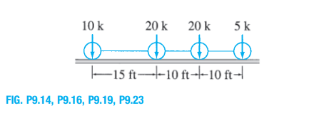
Trending now
This is a popular solution!
Step by step
Solved in 4 steps with 4 images
- B. In Fig. below; rod AB rotates about an axis through A and is connected to block D by a flexible and inextensible cable. Determine the linear velocity of block D when 0 = tan! ( 3 /4 ), and the angular velocity of AB is 2.5 rad / sec counterclockwise. Fig.2.B BB-Determine the moment of inertia of the shaded area of the figure below about y axis only. Fig.1 BGate AB in fig.4 is a quarter of circle 6m wide into the paper. Find the force Fjust sufficient to prevent rotation about hinge B. Neglect the weight of the gate.
- p1= 144 p2= 133Calculate for the support reactionsP=51The shorter legs of two 6”x 4” x 1⁄2” angles arewelded to a 12”-20.7-lb channel. Determine themoments of inertia of the combined sectionwith respect to centroidal axes respectivelyparallel and perpendicular to the web of thechannel. For the 12”-20.7-lb channel, its area is 6.03 sq. in.; x̄=0.70; ȳ=0; web thickness t = 0.280"
- Draw the influence lines for the shear and bending moment at point B of the beam shown in Fig. P8.24.1.Develop the Lateral surface of a truncated right regular cylinder of base diameter 50mm and height 70mm being sectioned by an AIP (cutting plane) inclined at an angle 45° to HP and perpendicular to VP such that it bisects the axis. 2.Draw isometric view of frustum of the square pyramid with 40 mm base edge, 20 mm upper edge and height 40 mm. 3.Draw isometric view of a square prism with 20 mm base edge and 50 mm height resting centrally on of cylinder with 60 mm base diameter and height 30 mmDraw the influence lines for the shear and bending moment at point D of the beam shown in Fig. P8.23.