
Concept explainers
Videos
(a) Using the superposition theorem, determine the current through the 12
b. Convert both voltage sources to current sources and recalculate the current to the 12
c. How do the results of parts (a) and (b) compare?
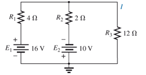
Fig. 9.125
(a)
The current through
Answer to Problem 1P
The current through
Explanation of Solution
Given:
The resistors values are
The voltage sources are
Concept Used:
Elements in the series have the same current.
Elements in the parallels have the same voltage.
Superposition theorem states that in any linear bilateral network having more than one source response in any one of the branches is equal to algebraic sum of the responses caused by individual source while rest of the sources are replaced by their internal impedances.
Short circuit the voltage source and open circuit the current source.
If the resistors are in series, then the value of the equivalent resistance for N series resistors is
If the resistors are in parallel, then the value of the equivalent resistance for N series resistors is
The special case for only two parallel resistors is
Current:
Current division is used to express the current across one of several parallel resistors in terms of current across the combination:
If there are two resistors in parallel then the current across second resistor is
Calculation:
Firstly, short circuit the voltage source
Conclusion:
Hence, the current through
(b)
The current through
Answer to Problem 1P
The current through
Explanation of Solution
Given:
The resistors values are
The voltage sources are
Concept Used:
Elements in the series have the same current.
Elements in the parallels have the same voltage.
Superposition theorem states that in any linear bilateral network having more than one source response in any one of the branches is equal to algebraic sum of the responses caused by individual source while rest of the sources are replaced by their internal impedances.
Short circuit the voltage source and open circuit the current source.
If the resistors are in series, then the value of the equivalent resistance for N series resistors is
If the resistors are in parallel, then the value of the equivalent resistance for N series resistors is
The special case for only two parallel resistors is
Current:
Current division is used to express the current across one of several parallel resistors in terms of current across the combination:
If there are two resistors in parallel then the current across second resistor is
Calculation:
Conclusion:
Hence, the current through
(c)
Compare the results of both the part (a) and (b).
Answer to Problem 1P
The results are similar in both the part (a) and (b).
Explanation of Solution
Given:
The resistors values are
The voltage sources are
Concept Used:
Elements in the series have the same current.
Elements in the parallels have the same voltage.
Superposition theorem states that in any linear bilateral network having more than one source response in any one of the branches is equal to algebraic sum of the responses caused by individual source while rest of the sources are replaced by their internal impedances.
Short circuit the voltage source and open circuit the current source.
Calculation:
The results are similar in both the part (a) and (b).
Conclusion:
Hence, the results are similar in both the part (a) and (b).
Want to see more full solutions like this?
Chapter 9 Solutions
Laboratory Manual for Introductory Circuit Analysis
Additional Engineering Textbook Solutions
Fundamentals of Applied Electromagnetics (7th Edition)
Electrical Engineering: Principles & Applications (7th Edition)
Applied Statics and Strength of Materials (6th Edition)
C++ How to Program (10th Edition)
Problem Solving with C++ (10th Edition)
Software Engineering (10th Edition)


- Write a program to perform the analysis required for Problem 8, Fig. 9.130(b), for any component values. Problem 8 Find the Thévenin equivalent circuit for the network external to the resistor R in each of the networks of Fig. 9.130.arrow_forward1) Transform the circuit in phasor domain representation.2) By using Nodal Analysis method, calculate the value of voltage at node, V1 and V23) Then, calculate the value of current, Ioarrow_forwardDetermine Zi for the network of Fig. 8.76 if Vi = 20 mV. Determine Zo for the network of Fig. 8.76 if Vi = 20 mV. Determine Vo for the network of Fig. 8.76 if Vi = 20 mV.arrow_forward
- Please answer quickly "In ac circuits, Kirchhoff s Voltage Law (KVL) states that in any given electric network, the phasor sum of the voltage rises and voltage drops within a node is always equal to zero." True False In ac circuit solution using KCL, the maximum number of independent equation/s can be used is equal to the number of major nodes." True False Norton's theorem is a network analysis method that allows a portion of a circuit to be isolated while the remianing portion of the network is replaced with an equivalent network (a parallel voltage source to an equivalent impedance). True Falsearrow_forwardUsing the Millman’s theorem, find the current through and voltage across the resistor RL of Fig. 9.144arrow_forwardthe current through the 9K22 resistor using Curret divider rule in fig . below is --------- MAarrow_forward
- If I0=4<0°(phasor) A in the circuit given below, calculate the current Ixarrow_forwardA circuit is given below. Compute for the algebraic sum of potential difference for the following electrical loops using KVL: abca abdca acda abcda acbda Show your systematic solutions.arrow_forward9.43 Find the current Io in the circuit shown in fig. 9.50arrow_forward
 Introductory Circuit Analysis (13th Edition)Electrical EngineeringISBN:9780133923605Author:Robert L. BoylestadPublisher:PEARSON
 Delmar's Standard Textbook Of ElectricityElectrical EngineeringISBN:9781337900348Author:Stephen L. HermanPublisher:Cengage Learning
 Programmable Logic ControllersElectrical EngineeringISBN:9780073373843Author:Frank D. PetruzellaPublisher:McGraw-Hill Education
 Fundamentals of Electric CircuitsElectrical EngineeringISBN:9780078028229Author:Charles K Alexander, Matthew SadikuPublisher:McGraw-Hill Education
 Electric Circuits. (11th Edition)Electrical EngineeringISBN:9780134746968Author:James W. Nilsson, Susan RiedelPublisher:PEARSON
 Engineering ElectromagneticsElectrical EngineeringISBN:9780078028151Author:Hayt, William H. (william Hart), Jr, BUCK, John A.Publisher:Mcgraw-hill Education,