
Videos
Using Fig. 9.45, design a problem to help other students better understand admittance.
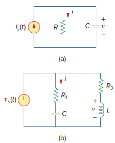
Figure 9.45
Design a problem to make better understand about the admittance using Figure 9.45.
Explanation of Solution
Problem design:
Determine the value of current
Formula used:
Write the expression to convert the time domain expression into phasor domain.
Here,
A is the magnitude,
t is the time, and
Write the expression to calculate the impedance of the passive elements resistor, inductor and capacitor.
Here,
Calculation:
(a)
The Figure 9.45(a) is redrawn as Figure 1 by assuming the values for the respective elements.
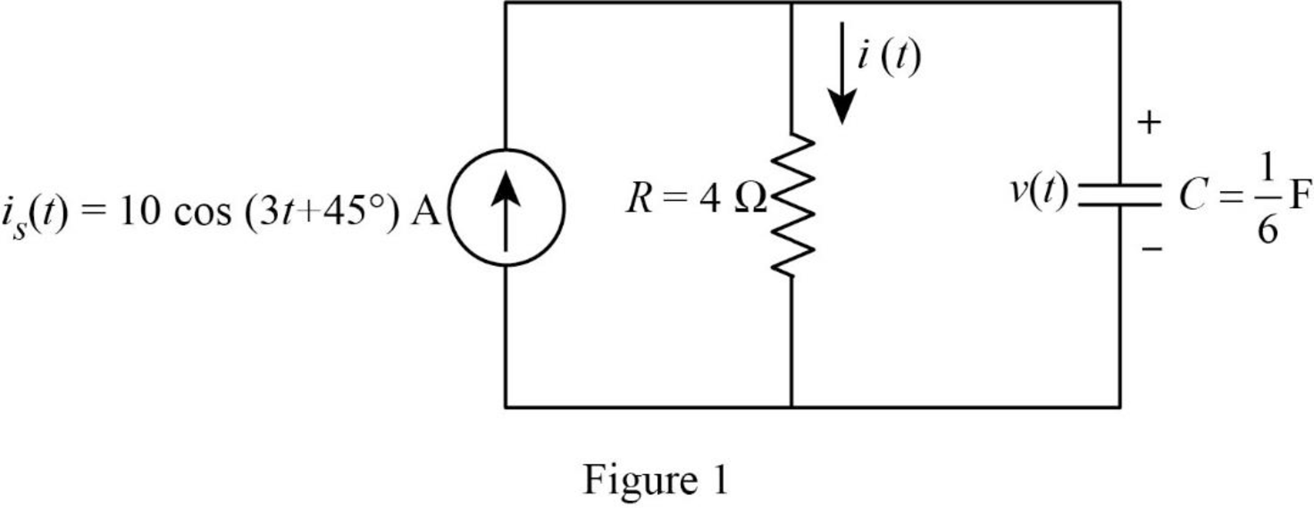
Refer to Figure 1, the current equation is,
Here, angular frequency
Use the equation (1) to express the above equation in phasor form.
Substitute
Substitute
The Figure 1 is redrawn as impedance circuit in the following Figure 2.
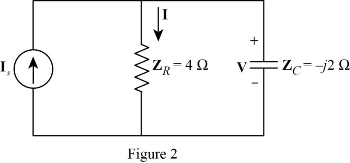
Apply current division rule on Figure 2 to find
Substitute
Use the equation (1) to express the above equation in time domain form.
Substitute
Refer to Figure 2, the voltage across the impedance
Substitute
Use the equation (1) to express the above equation in time domain form.
Substitute
Therefore, the value of current
(b)
The Figure 9.45(b) is redrawn as Figure 3 by assuming the values for the respective elements.
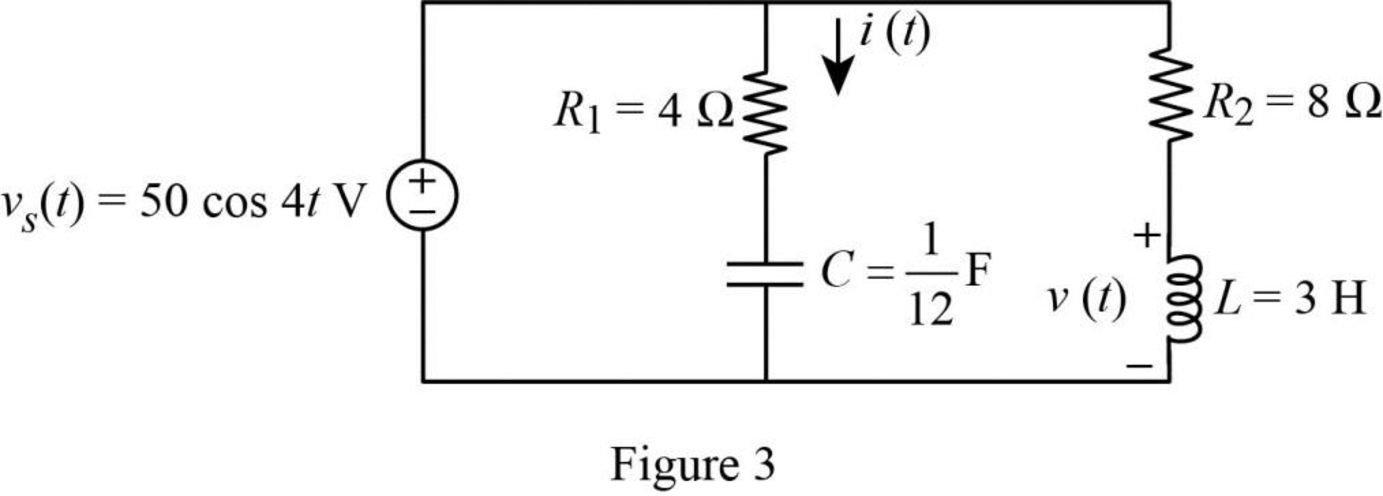
Refer to Figure 3, the voltage equation is,
Here, angular frequency
Use the equation (1) to express the above equation in phasor form.
Substitute
Substitute
Substitute
Substitute
The Figure 3 is redrawn as impedance circuit in the following Figure 4.
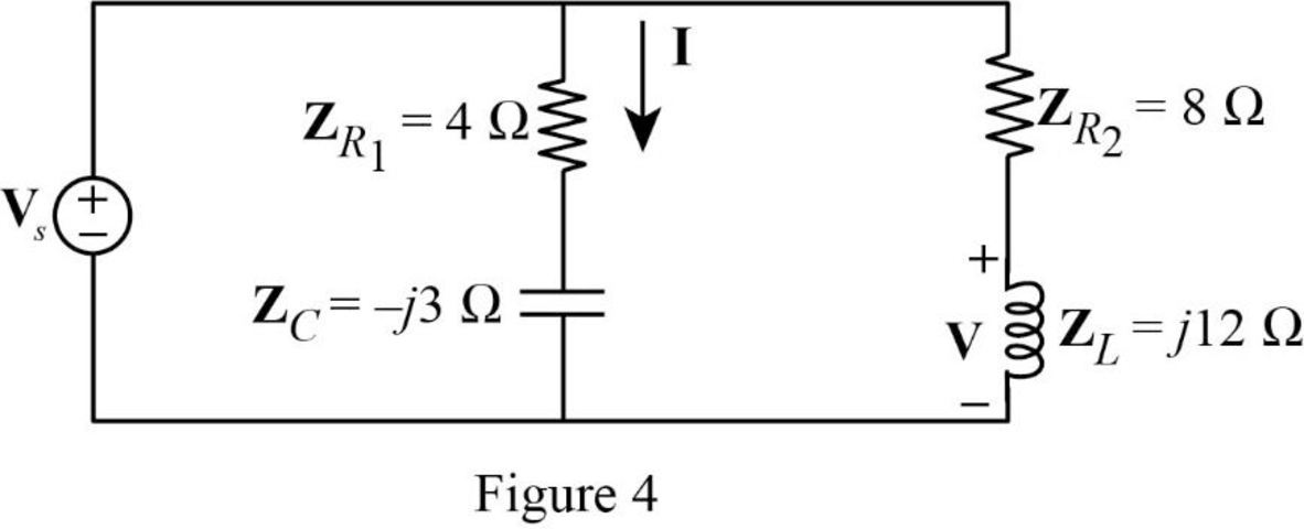
Refer to Figure 4, the impedances
Write the expression to calculate the equivalent impedance of the series connected impedances
Refer to Figure 4, the source voltage
Write the expression to calculate the current
Substitute
Substitute
Use the equation (1) to express the above equation in time domain form.
Substitute
Apply voltage division rule on Figure 4 to find
Substitute
Use the equation (1) to express the above equation in time domain form.
Substitute
Therefore, the value of current
Conclusion:
Thus, the problem to make better understand about the admittance using Figure 9.45 is designed.
Want to see more full solutions like this?
Chapter 9 Solutions
Fundamentals of Electric Circuits


- A 6.36 μF capacitor is connected in parallel with a resistance of 500Ω and the combination is connected in series with a 500Ω resistor. The whole circuit is connected across an ac source given by e=300sin(ωt) + 100 sin(3ωt + 30°). If ω = 314 rad/s. find: a)Irms b)Vrms c)total active power d)total power factor e)total reactive power f)total apparent powerarrow_forward9. A capacitor has a resistance of 80ohms when connected to a 50 Hz supply. Calculate the value of capacitance A. 39.79 microfarad B. 39.97 microfarad C. 93.79 microfarad D. 93.97 microfaradarrow_forwardA 160 μF capacitor is connected in series with a 10 Ω resistor. Write the equation of the current when the voltage is 220 Vp? a. 11.4 sin (377t + 59) b. 8.9 sin (377t – 46) c. 9.8 sin (377t + 52) d. 7.2 sin (377t + 46)arrow_forward
- A transmission line has a capacitance of 25 pF / ft. and an inductance of 0.15 µh / ft. Determine the characteristic impedance of the line.arrow_forwardIf a phasor representation of a current is given by I = 70.7 ∠45° A, it is equivalent toarrow_forwardb) Find the rms current flowing in an AC capacitive circuit when a 4μF capacitor is connected across a 880V, 60Hz supply.arrow_forward
- A resistor'R' with resistance value of 24 ohm, an inductor 'L' with inductance 20mH, and a capacitor 'C' with capacitance 50 micro Farrad are connected in series with a AC voltage v(t) where v(t) = 50 cos (2 vt + 30 degrees) v. Determine the current i(t) and total impedance if the frequency f is i. 60 Hz ii. 400Hzarrow_forwardThe voltage across a capacitor C is equal to v(t) = 8 cos(1000t) V. Determine the current i(t) through the capacitor at time t. C=100mu,F and t=8arrow_forwardCapacitance= 10uF , t≈65 μs, Vfinal=4VPlot capacitor current and voltage graphs. NOTE: if you want you can use falstad online circuit simulator.arrow_forward
- The current through a 0.5 F capacitor is i(t) = 6(1 - et) A, with-t in seconds. Determine the power in Watts at t = 2 s. Assume voltage at the start time of t = 0 is v(O) = 0.arrow_forwardAn inductor having an impedance of 6 + j8 is connected across a 200v supply. The real power supplied to it is watts. choices: 4000 3200 2400 1200arrow_forward1. What impedance vector 0 – j22 represents:A. A pure resistance.B. A pure inductance.C. A pure capacitance.D. An inductance combined with a resistance.arrow_forward
 Delmar's Standard Textbook Of ElectricityElectrical EngineeringISBN:9781337900348Author:Stephen L. HermanPublisher:Cengage Learning