
Concept explainers
Videos
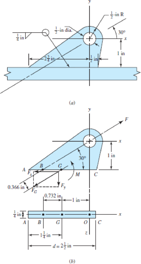
Brackets, such as the one shown, are used in mooring small watercraft. Failure of such brackets is usually caused by bearing pressure of the mooring clip against the side of the hole. Our purpose here is to get an idea of the static and dynamic margins of safety involved. We use a bracket 1/4 in thick made of hot-rolled 1018 steel, welded with an E6010 electrode. We then
assume wave action on the boat will create force F no greater than 1200 lbf.
(a) Determine the moment M of the force F about the centroid of the weld G. This moment produces a shear stress on the throat resisting bending action with a “tension” at A and “compression” at C.
(b) Find the force component Fy that produces a shear stress at the throat resisting a “tension” throughout the weld.
(c) Find the force component Fx that produces an in-line shear throughout the weld.
(d) Using Table 9–2, determine A, Iu, and I for the bracket.
(e) Find the shear stress τ1 at A due to Fy and M, the shear stress τ2 due to Fx, and combine to find τ.
(f) Find the factor of safety guarding against shear yielding in the weldment. Since the weld material is comprised of a mix of the electrode material and the base material, take the conservative approach of utilizing the strength of the weaker material.
(g) Find the factor of safety guarding against a static failure in the parent metal at the weld.
(h) Assuming the force F alternates between zero and 1200 lbf, find the factor of safety guarding against a fatigue failure in the weld metal using a Gerber failure criterion.
(a)
The moment
Answer to Problem 52P
The moment
Explanation of Solution
Write the expression for moment about
Here, force is
Conclusion:
Substitute
Thus, the moment
(b)
The force component
Answer to Problem 52P
The force component
Explanation of Solution
Write the expression for component of force
Here, force is
Conclusion:
Substitute
Thus, the force component
(c)
The force component
Answer to Problem 52P
The force component
Explanation of Solution
Write the expression for component of force
Here, force is
Conclusion:
Substitute
Thus, the force component
(d)
The area of throat, unit second moment of area and second area moment by using the Table
Answer to Problem 52P
The throat area is
The unit second moment of area is
The second area moment is
Explanation of Solution
Write the expression for throat area.
Here, thickness of weld is
Write the expression for unit second moment of area.
Here, thickness of weld is
Write the expression for second area moment about an axis
Here, thickness of weld is
Conclusion:
Substitute
Thus, the throat area is
Substitute
Thus, the unit second moment of area is
Substitute
Thus, second area moment is
(e)
The shear stress
The shear stress
The combined maximum shear stress
Answer to Problem 52P
The shear stress
The shear stress
The maximum shear stress is
Explanation of Solution
Write the expression for shear stress due to
Here, force in y-direction is
Write the expression for shear stress due to
Here, force in x-direction is
Write the expression for resultant shear stress at the throat plane.
Here, shear stress due to
Write the expression for secondary shear stress.
Here, Moment is
Write the expression for maximum shear stress.
Here, resultant shear stress at the throat plane is
Conclusion:
Substitute
Thus, the shear stress
Substitute
Thus, the shear stress
Substitute
Substitute
Substitute
Thus, the maximum shear stress is
(f)
The factor of safety guarding against shear yielding in the weldment.
Answer to Problem 52P
The factor of safety guarding against shear yielding in the weldment is
Explanation of Solution
Write the expression for factor of safety against guiding against shear yielding in weldment.
Here, yield stress is
Conclusion:
Refer to member of
Substitute
Thus, the factor of safety guarding against shear yielding in the weldment is
(g)
The factor of safety guarding against a static failure in the parent metal at the weld.
Answer to Problem 52P
The factor of safety guarding against a static failure in the parent metal at the weld is
Explanation of Solution
Write the expression for shear stress.
Here, force along x-direction is
Write the expression for normal stress along y-direction.
Here, force along x-direction is
Write the expression for von misses stress theory.
Here, normal stress is
Write the expression for factor of safety.
Here, yield stress is
Conclusion:
Substitute
Substitute
Substitute
Substitute
Thus, the factor of safety guarding against a static failure in the parent metal at the weld is
(h)
The factor of safety guarding against a fatigue failure in the weld metal using Gerber failure criterion.
Answer to Problem 52P
The factor of safety guarding against a fatigue failure in the weld metal using Gerber failure criterion is
Explanation of Solution
Write the expression for surface factor.
Here, ultimate tensile strength is
Write the expression for effective diameter.
Here, thickness of weld is
Write the expression for size factor.
Here, effective diameter is
Write the expression for equivalent strength.
Here, ultimate tensile strength is
Write the expression for endurance limit.
Here, surface factor is
Write the expression for axial shear stress.
Here, surface factor for shear is
Write the expression for factor of safety of Gerber criterion.
Here, maximum shear is
Conclusion:
Substitute
Substitute
Substitute
Substitute
Substitute
Substitute
Substitute
Thus, the factor of safety guarding against a fatigue failure in the weld metal using Gerber failure criterion is
Want to see more full solutions like this?
Chapter 9 Solutions
Shigley's Mechanical Engineering Design (McGraw-Hill Series in Mechanical Engineering)


- A sign for an automobile service station is supported by two aluminum poles of hollow circular cross section, as shown in the figure. The poles are being designed to resist a wind pressure of 75 lb/ft" against the full area of the sign. The dimensions of the poles and sign are hx= 20 ft, /r =5 ft, and h = 10 ft. To prevent buckling of the walls of the poles, the thickness e is specified as one-tenth the outside diameter d. (a) Determine the minimum required diameter of the poles based upon an allowable bending stress of 7500 psi in the aluminum. (b) Determine the minimum required diameter based upon an allowable shear stress of 300 psi.arrow_forwardA rigid bar of weight W = 750 lb hangs from three equally spaced wires: two of steel and one of aluminum (see figure). The diameter of the wires is 1/8 in. Before they were loaded, all three wires had the same length. What temperature increase T in all three wires will result in the entire load being carried by the steel wires? (Assume Es= 30 × 106 psi, as= 6.5 × 10⁻⁶ /'F, and aa= 12 × 10-6F.)arrow_forwardAn aluminum bar has length L = 6 ft and diameter d = 1.375 in. The stress-strain curse for the aluminum is shown in Fig. 1.34. The initial straight, line part of the curve has a slope (modulus of elasticity) of 10.6 × 10⁶ psi. The bar is loaded by tensile forces P = 44.6 k and then unloaded. (a) That is the permanent set of the bar? (b) If the bar is reloaded. what is the proportional limit? hint: Use the concepts illustrated in Figs. l.39b and 1.40.arrow_forward
- Three round, copper alloy bars having the same length L but different shapes are shown, in the figure. The first bar has a diameter d over its entire length, the second has a diameter d over one-fifth of its length, and the third has a diameter d over one-fifteenth of its length. Elsewhere, the second and third bars have a diameter Id. All three bars are subjected to the same axial load P. Use the following numerical data: P = 1400 kN, L = 5m,d= 80 mm, E= 110 GPa. and v = 0.33. (a) Find the change in length of each bar. (b) Find the change in volume of each bar.arrow_forwardSolve the preceding problem if the internal pressure is 3,85 MPa, the diameter is 20 m, the yield stress is 590 MPa, and the factor of safety is 3.0. (a) Determine the required thickness to the nearest millimeter. (b) If the tank wall thickness is 85 mm, what is the maximum permissible internal pressure?arrow_forwardRepeat Problem 2.3-18, but assume that the bar is made of copper alloy. Calculate the displacements SBand Scif P = 50 kips, L = 5 ft = 3/5 in., b1= 2.75 in., b2= 3 in., and E = 16,000 ksi.arrow_forward
- A pinned-end strut of aluminum (E = 10,400 ksi) with a length L = 6 ft is constructed of circular tubing with an outside diameter d = 1 in. (sec figure). The strut must resist an axial load F = 4 kips with a factor of safety n = 2.0 with respect to the critical load. Determine the required thickness t of the tube.arrow_forwardRepeat Problem 2.4-8, but assume that the bar is made of aluminum alloy and that BC is prismatic. Assume that P = 20 kim. L = 3 ft.t = 314 in., b1 2m.b 2.Sin.andElO.400ksi.arrow_forwardA high-strength steel bar used in a large crane has a diameter d = 2.00 in. (sec figure). The steel has a modulus of elasticity E = 29 × 10 psi and Poisson’s ratio is v = 0.29. Because of clearance requirements, the diameter of the bar is limited to 2.001 in. when it is compressed by axial forces. What is the largest compressive load Pmaxthat is permitted?arrow_forward
- Repeat Problem 3.3-1, but now use a circular tube with outer diameter d0= 2.5 in. and inner diameter di= 1.5 in.arrow_forwardTwo sections of steel drill pipe, joined by bolted flange plates at Ä are being tested to assess the adequacy of both the pipes. In the test, the pipe structure is fixed at A, a concentrated torque of 500 kN - m is applied at x = 0.5 m, and uniformly distributed torque intensity t1= 250 kN m/m is applied on pipe BC. Both pipes have the same inner diameter = 200 mm. Pipe AB has thickness tAB=15 mm, while pipe BC has thickness TBC= 12 mm. Find the maximum shear stress and maximum twist of the pipe and their locations along the pipe. Assume G = 75 GPa.arrow_forwardA small lab scale has a rigid L-shaped frame ABC consisting of a horizontal aim AB (length b = 30 cm) and a vertical arm BC (length c = 20 cm) pivoted at point B. The pivot is attached to the outer frame BCD that stands on a laboratory bench. The position of the pointer at C is controlled by two parallel springs, each having a spring constant k = 3650 N/m. that are attached to a threaded rod. The pitch of the threads is p = 1.5 mm. If the weight is 65 N. how many revolutions of the nut are required to bring the pointer back to the mark?arrow_forward
 Mechanics of Materials (MindTap Course List)Mechanical EngineeringISBN:9781337093347Author:Barry J. Goodno, James M. GerePublisher:Cengage Learning