Loose Leaf for Engineering Circuit Analysis Format: Loose-leaf
9th Edition
ISBN: 9781259989452
Author: Hayt
Publisher: Mcgraw Hill Publishers
bartleby

Videos

Textbook Question
Book Icon
Chapter 9, Problem 62E

Determine expressions for vC(t) and iL(t) in Fig. 9.59 for the time windows (a) 0 < t <2 μs and (b) t > 2 μs.
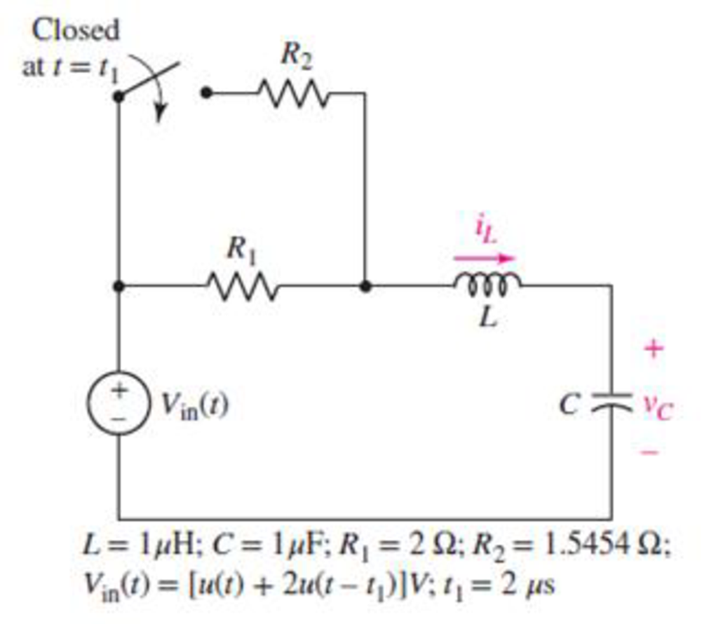
Chapter 9, Problem 62E, Determine expressions for vC(t) and iL(t) in Fig. 9.59 for the time windows (a) 0  t 2 s and (b) t

FIGURE 9.59

(a)

Expert Solution
Check Mark
To determine

Determine expressions for vC(t) and iL(t) in Fig. 9.59 for the time windows 0<t<2 μs.

Answer to Problem 62E

The expressions for vC(t) is 1+e(106)t(106t1) V and the expressions for iL(t) is (106)te106t A for the time windows 0<t<2 μs.

Explanation of Solution

Given Data:

The range of the time is 0<t<2 μs.

Formula used:

The expression for the exponential damping coefficient or the neper frequency for series RLC circuit is as follows:

α=R2L (1)

Here,

α is the exponential damping coefficient or the neper frequency of series RLC circuit,

R is the resistance of a series RLC circuit,

L is the inductance of a series RLC circuit.

The expression for the resonant frequency for series RLC circuit is as follows:

ω0=1LC (2)

Here,

ω0 is the resonant frequency of series RLC circuit and

C is the capacitance of a series RLC circuit.

The expression for complete natural response for source free series RLC circuit is:

vC(t)=vf+vn (3)

Here,

vC(t) is voltage across capacitor for t>0,

vf is forced response and

vn is the natural response.

The expression for the critically damped natural response of the series RLC circuit is as follows:

vn=eαt(A1t+A2) V (4)

Here,

vn is the natural response of the parallel RLC circuit,

A1 and A2 are arbitrary constants and

t is the time.

Calculation:

The unit-step forcing function as a function of time which is zero for all values of its argument less than zero and which is unity for all positive values of its argument.

u(tt0)={0   t<t01   t>t0

Here,

t0 is the time at which the argument of the function becomes zero.

So, at t=0 the voltage Vin(t)=[u(t)+2u(tt1)] V independent current source is equal to 0 V.

Since the series RLC circuit is source free at t<0 so, the voltage across the 1 μF capacitor is 0 V and the current flowing through μH is 0 A.

The capacitor does not allow sudden change in the voltage and the inductor does not allow sudden change in the current.

So,

vC(0+)=vC(0)

And,

iL(0+)=iL(0)

Therefore, the voltage across the capacitor at t=0 is 0 V and the current flowing through inductor at t=0 is 0 A.

At t>0 the voltage Vin(t)=[u(t)+2u(tt1)] V independent current source is equal to 1 V.

The redrawn circuit diagram is given in Figure 1 at t=0+.

Loose Leaf for Engineering Circuit Analysis Format: Loose-leaf, Chapter 9, Problem 62E , additional homework tip  1

Refer to the redrawn Figure 1:

Substitute 2 Ω for R and μH for L in the equation (1).

α=2 Ω(2)(μH)=Ω(2)(1×10⁶ H)                                                       {1 μH=106 H}  =106 s1

Substitute μH for L and 1 μF for C in equation (2).

ω0=1(μH)×(1 μF)=1(1×10⁶ H)×(1×10⁶ F)                                        {1 μH=106 H1 μF=106 F}=11×1012 s1=106 rad/s

Here, the resonant frequency is equal to the exponential damping coefficient.

Therefore, the response of the circuit is critically damped.

At t>0 the voltage Vin(t)=[u(t)+2u(tt1)] V independent current source is equal to 1 V.

Therefore, the value of forced response vf is 1 V.

Substitute 1 V for vf and eαt(A1t+A2) V for vn in equation (3).

vC(t)=1 V+eαt(A1t+A2) V

vC(t)=1+eαt(A1t+A2) V (5)

Substitute 0 for t in equation (3).

vC(0)=1+eα(0)(A1(0)+A2) V=1+(1)(A2) V

vC(0)=1+A2 V (6)

The voltage across the capacitor at t=0 is 0 V.

Substitute 0 V for vC(0) in equation (6).

0 V=1+A2 V

Rearrange for A2.

A2=1

The expression for the current flowing through 1 μF capacitor in the series RLC circuit is as follows:

iC=iL

So, the current flowing through 1 μF capacitor is 0 A.

The expression for the current flowing through the 1 μF capacitor is as follows:

iC(t)=Cdv(t)dt (7)

v(t) is the voltage across the 1 μF capacitor for t=0+.

Substitute 1+eαt(A1t+A2) V for v(t) in equation (7).

iC(t)=Cd(1+eαt(A1t+A2) V)dt

Rearrange for iC(t)C.

iC(t)C=d(1+eαt(A1t+A2) V)dt

iC(t)C=(0+A1eαtA1αteαtαeαtA2) V (8)

Substitute 0 for t in equation (8).

iC(0)C=(A1eα(0)A1α(0)eα(0)αeα(0)A2) V=A1(0)0α(1)A2 V

iC(0)C=A1αA2 V (9)

The current flowing through 1 μF capacitor is 0 A.

Substitute 1 for A2 and 106 s1 for α in equation (9).

iC(0)C=A1(106 s1)(1)V (10)

Substitute 0 A for iC(0) and 1 μF for C in equation (10).

0 A1 μF=A1(106 s1)(1)0=A1+106 s1

Rearrange for A1.

A1=106 s1

Substitute 106 s1 for A1, 1 for A2 and 106 s1 for α in equation (10).

vC(t)=1+e(106 s1)t((106 s1)t1) V (11)

The expression for the current flowing through the μH inductor in the circuit is as follows:

iL(t)=CdvC(t)dt (12)

Substitute 1+e(106 s1)t((106 s1)t1) V for vC(t) in equation (12).

iL(t)=Cd(1+e(106 s1)t((106 s1)t1) V)dt=Cd(1(106 s1)te106te106t)dt  V/s=C(0(106 s1)e106t+(106 s1)(106)te106t+(106)e106t)  V/s

iL(t)=C((106 s1)(106)te106t) V/s (13)

Substitute 1 μF for C in equation (13).

iL(t)=(1 μF)((106 s1)(106)te106t) V/s=(1×106 F)((106 s1)(106)te106t) V/s

iL(t)=(106s1)te106t A (14)

Conclusion:

Thus, the expressions for vC(t) is 1+e(106 s1)t((106 s1)t1) V and the expressions for iL(t) is (106 s1)te106t A for the time windows 0<t<2 μs.

(b)

Expert Solution
Check Mark
To determine

Determine expressions for vC(t) and iL(t) in Fig. 9.59 for the time windows t>2 μs.

Answer to Problem 62E

The expressions for vC(t) is:

[3V+e(4.3589×10⁵ s1)(t2 μs)(2.406cos(9×10⁵ rad/s(t2 μs))0.8645sin(9×10⁵ rad/s(t2 μs))) V] andthe expressions for iL(t) is:

e(4.3589×10⁵ s1)(t2 μs){0.2707cos(9×10⁵ rad/s(t2 μs))+2.542sin(9×10⁵ rad/s(t2 μs))} A for the time window t<2 μs.

Explanation of Solution

Formula used:

The expression for the damped natural frequency in series RLC circuit is:

ωd=ω02α2rad/s (15)

Here,

ωd is the damped natural frequency.

The expression for natural response for series RLC circuit is:

vn=eαt(B1cosωdt+B2sinωdt) V (16)

Here,

B1 and B2 is arbitrary constant for underdamped response,

α is the exponentially decaying constant and

ωd is the damped resonant frequency.

Calculation:

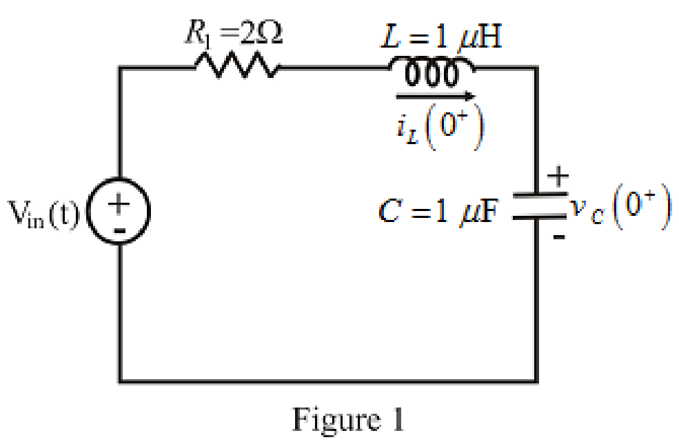
The redrawn circuit diagram is given in Figure 2 at t=2 μs.

Loose Leaf for Engineering Circuit Analysis Format: Loose-leaf, Chapter 9, Problem 62E , additional homework tip  2

Refer to the redrawn Figure 2:

The initial condition of the voltage across the μF capacitor and the current through the μH inductor is calculated at t=2 μs.

Substitute 2 μs for t in equation (11).

vC(2 μs)=1+e(106 s1)(2 μs)((106 s1)(2 μs)1) V=1+e(106 s1)(2×10⁶ s)((106 s1)(2×10⁶ s1)1) V                  {1 μs=106 s}=1+(0.135335)(21) V=1+(0.4060) V

vC(2 μs)=0.594 V

So, the initial condition of the voltage across the μF capacitor at t=2 μs is 0.594 V.

Substitute 2 μs for t in equation (14).

iL(2 μs)=(106 s1)(2 μs)e106(2 μs) A=(106 s1)(2×10⁶ s)e106(2×10⁶ s) A                                      {1 μs=106 s}=(2)(0.135335) A =0.2707 A

So, the initial condition ofthe current through the μH inductor at t=2 μs is 0.2707 A.

At t>2 μs the voltage Vin(t)=[u(t)+2u(tt1)] V independent current source is equal to 3 V.

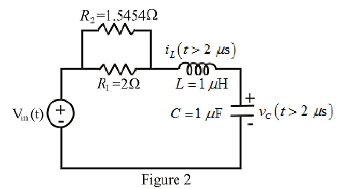
The expression for the equivalent resistor when resistors are connected in parallel is as follows:

1Req=1R1+1R2+......+1RN (17)

Here,

R1, R2,…, RN are the resistance of the resistors connected in parallel.

Ω and 1.5454 Ω resistor are connected in parallel.

So, form equation (15),

1Req=1Ω+11.5454 Ω=1.14708 Ω1

Rearrange for Req.

Req=11.14708 Ω =0.8718 Ω

The redrawn circuit diagram is given in Figure 3.

Loose Leaf for Engineering Circuit Analysis Format: Loose-leaf, Chapter 9, Problem 62E , additional homework tip  3

Refer to the redrawn Figure 3:

Substitute 0.8718 Ω for R and μH for L in equation (1).

α=0.8718 Ω(2)(μH)=0.8718 Ω(2)(1×10⁶ H)                                                       {1 μH=106 H}  =4.3589×10⁵ s1

Substitute μH for L and 1 μF for C in equation (2).

ω0=1(μH)×(1 μF)=1(1×10⁶ H)×(1×10⁶ F)                                        {1 μH=106 H1 μF=106 F}=11×1012 s1=106 rad/s

Here, the resonant frequency is greater than the exponential damping coefficient.

Therefore, the response of the circuit is under-damped damped.

Substitute 4.3589×10⁵ s1 for α and 106 rad/s for ω0 in equation (4).

ωd=(106 rad/s)2(4.3589×105 s1)2=8.1×10¹¹rad/s=9×105rad/s

At t>2 μs the voltage Vin(t)=[u(t)+2u(tt1)] V independent current source is equal to 3 V.

Therefore, the value of forced response vf is 3 V.

Substitute 3V for vf and eαt(B1cosωdt+B2sinωdt) for vn in equation (3).

vC(t)=3V+eαt(B1cosωdt+B2sinωdt) V (18)

Apply time shift in equation (18).

vC(t)=3V+eα(t2 μs)(B1cosωd(t2 μs)+B2sinωd(t2 μs)) V (19)

Substitute 2 μs for t in equation (18).

vC(2 μs)=[3V+eα(2 μs2 μs)(B1cosωd(2 μs2 μs)+B2sinωd(2 μs2 μs)) V]=3V+(1)(B1cosωd(0)+B2sinωd(0)) V=3V+(1)(B1(1)+(0)) V

vC(2 μs)=3V+B1 V (20)

The initial condition of the voltage across the μF capacitor at t=2 μs is 0.594 V.

Substitute 0.594 V for vC(2 μs) in equation (20).

0.594 V=3V+B1 V

Rearrange for B1.

B1=3+0.594=2.406

The expression for the current flowing through 1 μF capacitor in the series RLC circuit is as follows:

iC=iL

So, the current flowing through 1 μF capacitor at t=2 μs is 0.2707 A.

The expression for the current flowing through the 1 μF capacitor at t=2 μs is as follows:

iC(2 μs)=CdvC(t)dt|t=2 μs

Here,

v(t) is the voltage across the 1 μF capacitor.

Rearrange for iC(2 μs)C

dvC(t)dt|t=2 μs=iC(2 μs)C (21)

Substitute 0.2707 A for iC(2 μs) and 1 μF for C in equation (21).

dvC(t)dt|t=2 μs=0.2707 A1 μF=0.2707 A1×106 F                                            {1 μs=106 s}=270700 V/s

Substitute 3V+eα(t2 μs)(B1cosωd(t2 μs)+B2sinωd(t2 μs)) V for v(t) in equation (20).

dvC(t)dt=ddt(3V+eα(t2 μs)(B1cosωd(t2 μs)+B2sinωd(t2 μs)) V)=ddt(3+eα(t2 μs)B1cosωd(t2 μs)+eα(t2 μs)B2sinωd(t2 μs)) V

dvC(t)dt={0+(αeα(t2 μs)B1cosωd(t2 μs)ωdeα(t2 μs)B1sinωd(t2 μs))+(αeα(t2 μs)B2sinωd(t2 μs)+ωdeα(t2 μs)B2cosωd(t2 μs))} V/s (21)

Substitute 2 μs for t in equation (21).

dvC(t)dt|t=2 μs={(αeα(2 μs2 μs)B1cosωd(2 μs2 μs)ωdeα(2 μs2 μs)B1sinωd(2 μs2 μs))+(αeα(2 μs2 μs)B2sinωd(2 μs2 μs)+ωdeα(2 μs2 μs)B2cosωd(2 μs2 μs))} V/s={(αeα(0)B1cosωd(0)ωdeα(0)B1sinωd(0))+(αeα(0)B2sinωd(0)+ωdeα(0)B2cosωd(0))} V/s={(αB1(1)ωdeα(0)B1(0))+(αeα(0)B2(0)+ωd(1)B2(1))} V/s

dvC(t)dt|t=2 μs=(αB1+ωdB2) V/s (22)

Substitute 270700 V/s for dvC(t)dt|t=2 μs, 2.406 for B1, 4.3589×10⁵ s1 for α and 9×10⁵ rad/s for ωd in equation (22).

270700=(4.3589×10⁵)(2.406)+(9×10⁵)B2270700=1048751.34+(9×10⁵)B2

Rearrange for B2.

2707001048751.34=(9×10⁵)B2778051.34=(9×10⁵)B2B2=778051.349×105    =0.8645

Substitute 2.406 for B1, 0.8645 for B2, 4.3589×10⁵ s1 for α and 9×10⁵ rad/s for ωd in equation (19).

vC(t)=[3V+e(4.3589×10⁵ s1)(t2 μs)(2.406cos(9×10⁵ rad/s(t2 μs))0.8645sin(9×10⁵ rad/s(t2 μs))) V] (23)

Substitute 3V+eα(t2 μs)(B1cosωd(t2 μs)+B2sinωd(t2 μs)) V for v(t) in equation (13).

iL(t)=Cddt(3V+eα(t2 μs)(B1cosωd(t2 μs)+B2sinωd(t2 μs)) V)=Cddt(3+eα(t2 μs)B1cosωd(t2 μs)+eα(t2 μs)B2sinωd(t2 μs)) V

iL(t)=C{(αeα(t2 μs)B1cosωd(t2 μs)ωdeα(t2 μs)B1sinωd(t2 μs))+(αeα(t2 μs)B2sinωd(t2 μs)+ωdeα(t2 μs)B2cosωd(t2 μs))} V/s (24)

Substitute 1 μF for C, 2.406 for B1, 0.8645 for B2, 4.3589×10⁵ s1 for α and 9×10⁵ rad/s for ωd in equation (24).

iL(t)=(1 μF){([(4.3589×10⁵ s1)e(4.3589×10⁵ s1)(t2 μs)(2.406)cos(9×10⁵ rad/s(t2 μs))][(9×10⁵ rad/s)eV(t2 μs)(2.406)sin(9×10⁵ rad/s(t2 μs))])+([(4.3589×10⁵ s1)e(4.3589×10⁵ s1)(t2 μs)(0.8645)sin(9×10⁵ rad/s(t2 μs))][+(9×10⁵ rad/s)eα(t2 μs)(0.8645)cos(9×10⁵ rad/s(t2 μs))])} V/s=(1 μF)e(4.3589×10⁵ s1)(t2 μs){1048751.34cos(9×10⁵ rad/s(t2 μs))+2165400sin(9×10⁵ rad/s(t2 μs))+376826.905sin(9×10⁵ rad/s(t2 μs))778050cos(9×10⁵ rad/s(t2 μs))} V/s=(1×106 F)e(4.3589×10⁵ s1)(t2 μs){[270701.34cos(9×10⁵ rad/s(t2 μs))]+[2542226.905sin(9×10⁵ rad/s(t2 μs))]} V/s       {1 μF=106 F}iL(t)=e(4.3589×10⁵ s1)(t2 μs){0.2707cos(9×10⁵ rad/s(t2 μs))+2.542sin(9×10⁵ rad/s(t2 μs))} A

Conclusion:

Thus, the expressions for vC(t) is:

[3V+e(4.3589×10⁵ s1)(t2 μs)(2.406cos(9×10⁵ rad/s(t2 μs))0.8645sin(9×10⁵ rad/s(t2 μs))) V] and the expressions for iL(t) is:

e(4.3589×10⁵ s1)(t2 μs){0.2707cos(9×10⁵ rad/s(t2 μs))+2.542sin(9×10⁵ rad/s(t2 μs))} A for the time window t<2 μs.

Want to see more full solutions like this?

Subscribe now to access step-by-step solutions to millions of textbook problems written by subject matter experts!
Students have asked these similar questions
For the network shown below, the switch is closed on to position 1 when t = 0 and then moved to position 2 when t = 20 ms. Determine the voltage across the capacitor when t = 30 ms. Also plot the response of this circuit from time, t = 0 to t = 40 ms.
The phasor current Ib in the circuit  is 25 0 . mA.1. Find Ia, Ic, and Ig.2. If ω=1500 rad/s, write expressions for ia(t), ic(t), and ig(t).
Please plot Root Locus for G(S)=[7/S^2]. . please proper hand written Sketch.Other wise ready for Downvote.

Chapter 9 Solutions

Loose Leaf for Engineering Circuit Analysis Format: Loose-leaf

Ch. 9.7 - Alter the capacitor value and voltage source in...Ch. 9 - For a certain source-free parallel RLC circuit, R...Ch. 9 - Element values of 10 mF and 2 nH are employed in...Ch. 9 - If a parallel RLC circuit is constructed from...Ch. 9 - Prob. 4ECh. 9 - You go to construct the circuit in Exercise 1,...Ch. 9 - A parallel RLC circuit has inductance 2 mH and...Ch. 9 - Prob. 7ECh. 9 - A parallel RLC circuit has R = 1 k, L = 50 mH. and...Ch. 9 - Prob. 9ECh. 9 - Prob. 10ECh. 9 - The current flowing through a 5 resistor in a...Ch. 9 - For the circuit of Fig.9.40, obtain an expression...Ch. 9 - Consider the circuit depicted in Fig. 9.40. (a)...Ch. 9 - With regard to the circuit represented in Fig....Ch. 9 - (a) Assuming the passive sign convention, obtain...Ch. 9 - With regard to the circuit presented in Fig. 9.42,...Ch. 9 - Obtain expressions for the current i(t) and...Ch. 9 - FIGURE 9.43 Replace the 14 resistor in the...Ch. 9 - Design a complete source-free parallel RLC circuit...Ch. 9 - For the circuit represented by Fig. 9.44, the two...Ch. 9 - Prob. 21ECh. 9 - Prob. 22ECh. 9 - A critically damped parallel RLC circuit is...Ch. 9 - A source-free parallel RLC circuit has an initial...Ch. 9 - A critically damped parallel RLC circuit is...Ch. 9 - For the circuit of Fig. 9.45, is(t) = 30u(t) mA....Ch. 9 - Prob. 27ECh. 9 - The circuit of Fig. 9.44 is rebuilt such that the...Ch. 9 - Prob. 29ECh. 9 - Prob. 30ECh. 9 - The source-free circuit depicted in Fig. 9.1 is...Ch. 9 - (a) Graph the current i for the circuit described...Ch. 9 - Analyze the circuit described in Exercise 31 to...Ch. 9 - A source-free parallel RLC circuit has capacitance...Ch. 9 - Prob. 35ECh. 9 - Obtain an expression for vL(t), t 0, for the...Ch. 9 - For the circuit of Fig. 9.47, determine (a) the...Ch. 9 - (a) Design a parallel RLC circuit that provides a...Ch. 9 - The circuit depicted in Fig. 9.48 is just barely...Ch. 9 - When constructing the circuit of Fig. 9.48, you...Ch. 9 - The circuit of Fig. 9.22a is constructed with a...Ch. 9 - Prob. 42ECh. 9 - Prob. 43ECh. 9 - The simple three-element series RLC circuit of...Ch. 9 - Prob. 45ECh. 9 - Prob. 46ECh. 9 - Prob. 47ECh. 9 - With reference to the series RLC circuit of Fig....Ch. 9 - Obtain an expression for i1 as labeled in Fig....Ch. 9 - The circuit in Fig. 9.52 has the switch in...Ch. 9 - For the circuit in Fig. 9.52, determine the value...Ch. 9 - In the series circuit of Fig. 9.53, set R = 1 ....Ch. 9 - Evaluate the derivative of each current and...Ch. 9 - Consider the circuit depicted in Fig. 9.55. If...Ch. 9 - Prob. 55ECh. 9 - In the circuit shown in Fig. 9.56, (a) obtain an...Ch. 9 - Prob. 57ECh. 9 - For the circuit represented in Fig. 9.57, (a)...Ch. 9 - FIGURE 9.57 Replace the 1 resistor in Fig. 9.57...Ch. 9 - A circuit has an inductive load of 2 H, a...Ch. 9 - (a) Adjust the value of the 3 resistor in the...Ch. 9 - Determine expressions for vC(t) and iL(t) in Fig....Ch. 9 - The capacitor in the LC circuit in Fig. 9.60 has...Ch. 9 - Suppose that the switch in the circuit in Fig....Ch. 9 - The capacitor in the circuit of Fig. 9.63 is set...Ch. 9 - The physical behavior of automotive suspension...Ch. 9 - A lossless LC circuit can be used to provide...
Knowledge Booster
Background pattern image
Electrical Engineering
Learn more about
Need a deep-dive on the concept behind this application? Look no further. Learn more about this topic, electrical-engineering and related others by exploring similar questions and additional content below.
Similar questions
SEE MORE QUESTIONS
Recommended textbooks for you
Text book image
Introductory Circuit Analysis (13th Edition)
Electrical Engineering
ISBN:9780133923605
Author:Robert L. Boylestad
Publisher:PEARSON
Text book image
Delmar's Standard Textbook Of Electricity
Electrical Engineering
ISBN:9781337900348
Author:Stephen L. Herman
Publisher:Cengage Learning
Text book image
Programmable Logic Controllers
Electrical Engineering
ISBN:9780073373843
Author:Frank D. Petruzella
Publisher:McGraw-Hill Education
Text book image
Fundamentals of Electric Circuits
Electrical Engineering
ISBN:9780078028229
Author:Charles K Alexander, Matthew Sadiku
Publisher:McGraw-Hill Education
Text book image
Electric Circuits. (11th Edition)
Electrical Engineering
ISBN:9780134746968
Author:James W. Nilsson, Susan Riedel
Publisher:PEARSON
Text book image
Engineering Electromagnetics
Electrical Engineering
ISBN:9780078028151
Author:Hayt, William H. (william Hart), Jr, BUCK, John A.
Publisher:Mcgraw-hill Education,
Types of Systems; Author: Neso Academy;https://www.youtube.com/watch?v=IRdDcSO_fQw;License: Standard youtube license