
Videos
The ac bridge circuit of Fig. 9.85 is called a Wien bridge. It is used for measuring the frequency of a source. Show that when the bridge is balanced,
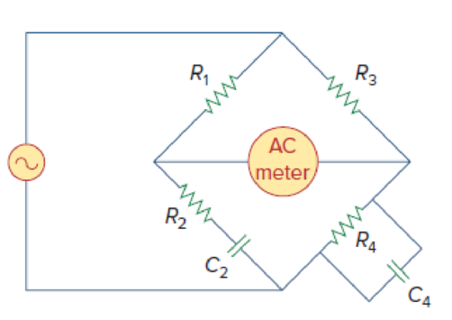
Figure 9.85
Show that when the bridge in Figure 9.85 is balanced the value of frequency is
Explanation of Solution
Given data:
Refer to Figure 9.85 in the textbook.
Formula used:
Write a general expression to calculate the impedance of a resistor.
Here,
Write a general expression to calculate the impedance of a capacitor.
Here,
Write a general expression to calculate the angular frequency.
Here,
Calculation:
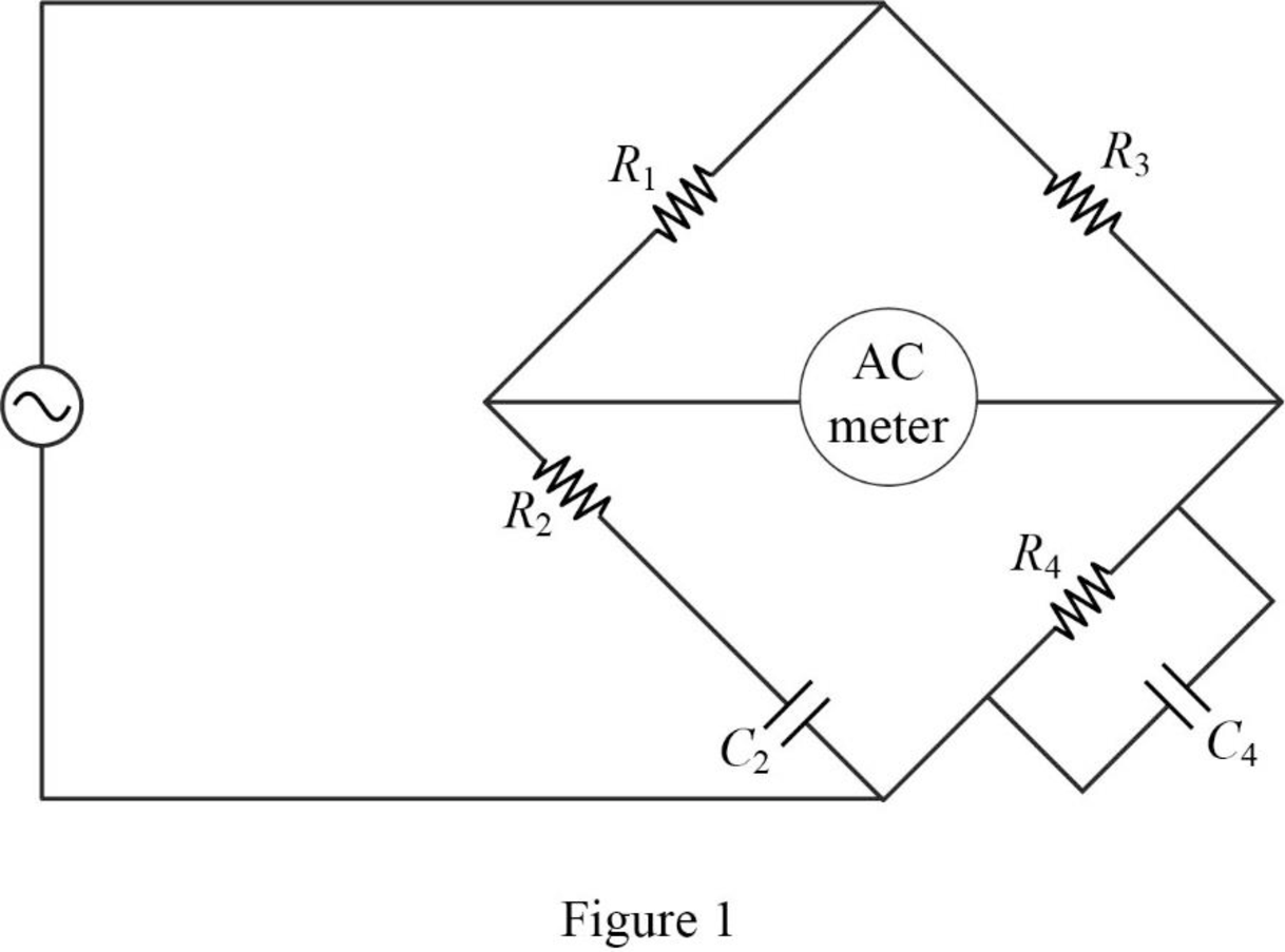
The given circuit is redrawn as shown in Figure 1.
Use equation (1) to find
Use equation (2) to find
Now, the impedance diagram of Figure 1 is drawn as shown in Figure 2.
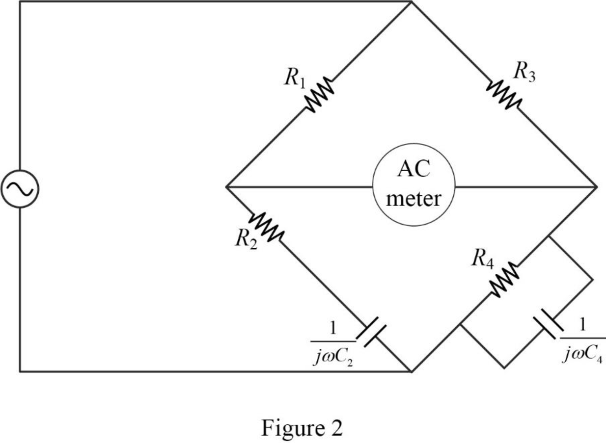
Refer to Figure 2, the impedance of resistor
Therefore, the equivalent impedance
Refer to Figure 2, the impedance of resistor
The equivalent impedance
Simplify the above equation as follows:
Let,
The balance of equation of an ac bridge is,
The above equation as rearranged as follows:
Substitute
Take the conjugate of denominator to rationalize the fraction in left hand side.
Equate the real and imaginary part in above equation.
Divide equation (4) by (5).
Simplify the above equation to find
Rearrange equation (3) to find
Substitute
Conclusion:
Thus, when the bridge is balanced, the value of frequency
Want to see more full solutions like this?
Chapter 9 Solutions
Fundamentals of Electric Circuits


- An inductor having an impedance of 6 + j8 is connected across a 200v supply. The real power supplied to it is watts. choices: 4000 3200 2400 1200arrow_forward70. Ideal inductors and capacitors are 90 degrees out of phase with each other. True False 71. Ideal inductors and resistors are 180 degrees out of phase with each other. True False 72. Impedance of a circuit can be represented or expressed in complex form. True Falsearrow_forward١** series RLC, R= 1 ohm, C= 0.2 F, L = 0.4H, Vs(t) = 10 Cos ( 5t - 45) V, the value of the capacitor complex power is?arrow_forward
- The current in an L-R-C series circuit has amplitude 0.120 Aand angular frequency 8.00 * 103 rad/s, and it has its maximum positivevalue at t = 0. The resistance is 95.0 Ω, the inductance is 6.50 mH,and the capacitance is 0.440 mF. For the resistor, inductor, and capacitor,find (a) the voltage amplitudes and (b) the instantaneous voltages att = 0.305 ms.arrow_forwardH = 3RM2cos(9ft) where f = frequency, t = time, and the remaining variables are either proportionality constants or material constants. What is the maximum value H could have (algebraic answer)arrow_forwardSince they are defined as X=1 and Y=10 Ω, respectively, in the circuit given below; What is the angle of the voltage phasor Vo? NOTE: Please enter your answer as 2 digits after the comma.arrow_forward
- The impedance, Z, of the circuit shown is Ω. choices: a (2.3 + j4.2) b (2.4 + j3.2) c (4.06 – j3.25) d (3.25 – j4.06)arrow_forwarda series r-c circuit takes a current whose equation is i=0.85sin(754t+pi/4) when connected to a source of emf having the equation e=340sin754t. calculate the capacitance of the capacitor, circuit power factor, and power.arrow_forwardA given RLC circuit (Resistor-Inductor-Capacitor) has the following components: R = 4.4 Ohms L = 0.0017 H C = 5.79 x10⁻⁶ F If this system is driven by an oscillating current with frequency f = 765 Hz, what is the Capacitive Reactance (XC) of this system?arrow_forward
- A coil with impedance 8+j6 Ω is connected in series with a capacitive reactance X. The series combination is connected in parallel with a resistor R. Given that the equivalent impedance of the resulting circuit is 2.5∠0°Ω, find the value of X and R.arrow_forwardA given RLC circuit (Resistor-Inductor-Capacitor) has the following components: R = 4.1 Ohms L = 0.0099 H C = 0.00011 F If this system is driven by an oscillating current with frequency f = 2,594 Hz, what is the Inductive Reactance (XL) of this system?arrow_forwardA 6.36 μF capacitor is connected in parallel with a resistance of 500Ω and the combination is connected in series with a 500Ω resistor. The whole circuit is connected across an ac source given by e=300sin(ωt) + 100 sin(3ωt + 30°). If ω = 314 rad/s. find: a)Irms b)Vrms c)total active power d)total power factor e)total reactive power f)total apparent powerarrow_forward
 Delmar's Standard Textbook Of ElectricityElectrical EngineeringISBN:9781337900348Author:Stephen L. HermanPublisher:Cengage Learning