
Concept explainers
Videos
The equation of the deflection curve for a cantilever beam is
- Describe the loading acting on the beam.
(a)
Load acting on the beam.
Answer to Problem 9.2.1P
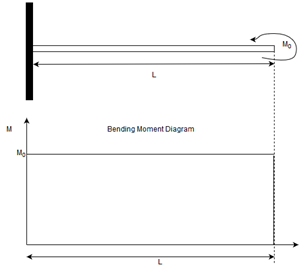
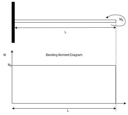
No load acting on the beam. Only moment
Explanation of Solution
Given:
Equation of the deflection curve:
The equation of the deflection curve for a cantilever beam,
Here,
Slope represents the first derivative of the deflection.
Therefore, differentiating the above w.r.t
Now, write the basic differential equation of deflection curve.
Here,
And
Differentiate the obtained slope equation w.r.t
Therefore, the beam is subjected to positive bending moment
Now, shear force to be calculated:
No shear force is acting on the beam.
Now, calculate load:
No load acting on the beam.
Therefore, only moment
(b)
Draw the moment diagram for the beam.
Answer to Problem 9.2.1P
Bending moment diagram:
Explanation of Solution
Given:
Equation of the deflection curve:
Bending moment diagram subjected to positive bending moment
Want to see more full solutions like this?
Chapter 9 Solutions
Mechanics of Materials (MindTap Course List)


- The deflection curve for a cantilever beam AB (see figure) is given by v=q0x2360L2EI(45L440L3x+15L2x2x4) Describe the load acting on the beam. Determine the reactions RAand M 4at the support.arrow_forward-6 Calculate the maximum deflection of a uniformly loaded simple beam if the span length L = 2.0 m, the intensity of the uniform load q = 2.0 kN/m, and the maximum bending stress = 60 MPa, The cross section of the beam is square, and the material is aluminum having modulus of elasticity E = 70 GPa. (Use the formulas of Example 9-1.)arrow_forwardA cantilever beam has two triangular loads as shown in the figure. Find an expression for beam deflection Scusing Superposition. Find the required magnitude of load intensity q2in terms of q0so that the deflection at C is zero. Find an expression for the deflection at C if both load intensities, qxand q2, are equal to q0.arrow_forward
- The cross section of a bimetallic strip is shown in the figure. Assuming that the moduli of elasticity for metals A and B are EA=168 GPa and EB= 90 GPa, respectively, determine the smaller of the two section moduli for the beam. (Recall that section modulus is equal to bending moment divided by maximum bending stress.) In which material does the maximum stress occur?arrow_forwardThe tapered cantilever beam AB shown in the figure has a solid circular cross section. The diameters at the ends A and B are dAand dB= 2dA, respectively. Thus, the diameter d and moment of inertia / at distance v from the free end are, respectively, in which IAis the moment of inertia at end A of the beam. Determine the equation of the deflection curve and the deflection SAat the free end of the beam due to the load P.arrow_forwardA fixed-end beam AB carries point load P acting at point C. The beam has a rectangular cross section (b = 75 mm, h = 150 mm). Calculate the reactions of the beam and the displacement at point C. Assume that E = 190 GPa.arrow_forward
- A rectangular beam with semicircular notches, as shown in part b of the figure, has dimensions h = 120 mm and h1= 100 mm. The maximum allowable bending stress in the plastic beam is emix = 6 M Pa, and the bending moment is M = 150 N · m. Determine the minimum permissible width bminof the beam.arrow_forward.20 Determine the plastic moment Mpfor beam having the cross section shown in the figure ey=210 MPa.arrow_forwardTwo identical, simply supported beams AB and CD are placed so that they cross each other at their midpoints (sec figure). Before the uniform load is applied, the beams just touch each other at the crossing point. Determine the maximum bending moments (mab)max* and (MCD)max beams AB and CD, respectively, due to the uniform load if the intensity of the load is q = 6.4 kN/m and the length of each beam is L = 4 m.arrow_forward
- A beam supporting a uniform load of intensity q throughout its length rests on pistons at points A, C and B (sec figure). The cylinders are filled with oil and are connected by a tube so that the oil pressure on each piston is the same. The pistons at A and B have diameter d1and the piston at C has diameter D2. (a) Determine the ratio of d2to d1so that the largest bending moment in the beam is as small as possible. Under these optimum conditions, what is the largest bending moment Mmaxin the beam? What is the difference in elevation between point C and the end supports?arrow_forwardA simple beam AB is subjected to couples M0and 2A0 acting as shown in the figure. Determine the angles of rotation 04and BBat the ends of the beam and the deflection S at point D where the load M0is applied.arrow_forwardDerive the equation of the deflection curve for beam AB with sliding support at A and roller at B* carrying a triangularly distributed load of maximum intensity q0(see figure). Also, determine the maximum deflection ôniill of the beam. Lsc the fourth-order differential equation of the deflection curve (the load equation).arrow_forward
 Mechanics of Materials (MindTap Course List)Mechanical EngineeringISBN:9781337093347Author:Barry J. Goodno, James M. GerePublisher:Cengage Learning