
Mechanics of Materials (MindTap Course List)
9th Edition
ISBN: 9781337093347
Author: Barry J. Goodno, James M. Gere
Publisher: Cengage Learning
expand_more
expand_more
format_list_bulleted
Concept explainers
Videos
Textbook Question
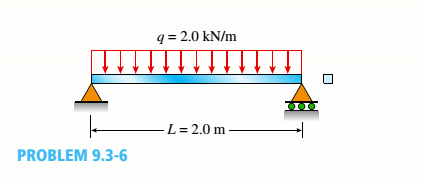
Chapter 9, Problem 9.3.6P
-6 Calculate the maximum deflection of a uniformly loaded simple beam if the span length L = 2.0 m, the intensity of the uniform load q = 2.0 kN/m, and the maximum bending stress
The cross section of the beam is square, and the material is aluminum having modulus of elasticity E = 70 GPa. (Use the formulas of Example 9-1.)
Expert Solution & Answer

Trending nowThis is a popular solution!

Chapter 9 Solutions
Mechanics of Materials (MindTap Course List)
Ch. 9 - The equation of the deflection curve for a...Ch. 9 - The equation of the deflection curve for a simply...Ch. 9 - -3 The deflection curve for a simple beam AB (see...Ch. 9 - The deflection curve for a simple beam AB (sec...Ch. 9 - The deflection curve for a cantilever beam AB (sec...Ch. 9 - The deflection curve for a cantilever beam AB (see...Ch. 9 - A simply supported beam is loaded with a point...Ch. 9 - A I-meter-long, simply supported copper beam (E =...Ch. 9 - A wide-flange beam (W 12 x 35) supports a uniform...Ch. 9 - A uniformly loaded, steel wide-flange beam with...
Ch. 9 - What is the span length L of a uniformly loaded,...Ch. 9 - -6 Calculate the maximum deflection of a uniformly...Ch. 9 - A cantilever beam with a uniform load (see figure)...Ch. 9 - A gold-alloy microbeam attached to a silicon wafer...Ch. 9 - Obtain a formula for the ratio c/maxof the...Ch. 9 - A cantilever beam model is often used to represent...Ch. 9 - B cams AB and CDE are connected using rigid link...Ch. 9 - -12 Derive the equation of the deflection curve...Ch. 9 - -13 Derive the equation of the deflection curve...Ch. 9 - -14 A cantilever beam AB supporting a triangularly...Ch. 9 - A cantilever beam has a length L = 12 ft and a...Ch. 9 - A simple beam with an overhang is subjected to d...Ch. 9 - -17 A cantilever beam AB is acted upon by a...Ch. 9 - -18 The beam shown in the figure has a sliding...Ch. 9 - -19 Derive the equations of the deflect ion curve...Ch. 9 - -20 Derive the equations of the deflection curve...Ch. 9 - -21 Derive the equations of the deflection curve...Ch. 9 - -22 Derive the equations of the deflection curve...Ch. 9 - -23 The beam shown in the figure has a sliding...Ch. 9 - -1 Derive the equation of the deflection curve for...Ch. 9 - -2 A simple beam AB is subjected to a distrib uted...Ch. 9 - -3 The simple beam AB shown in the figure has...Ch. 9 - -4 A beam with a uniform load has a sliding...Ch. 9 - -5 The distributed load acting on a cantilever...Ch. 9 - -6 A cantilever beam .4B is subjected to a...Ch. 9 - -7 A beam on simple supports is subjected to a...Ch. 9 - Derive the equation of the deflection curve for...Ch. 9 - -9 Derive the equations of the deflection curve...Ch. 9 - -10 Derive the equations of the deflection curve...Ch. 9 - A simply supported beam (E = 1600 ksi) is loaded...Ch. 9 - A simply supported beam (E = 12 GPa) carries a...Ch. 9 - Copper beam AB has circular cross section with a...Ch. 9 - Beam ABC is loaded by a uniform load q and point...Ch. 9 - A cantilever beam of a length L = 2.5 ft has a...Ch. 9 - A cantilever beam carries a trapezoidal...Ch. 9 - -5-7 A cantilever beam AB carries three equalaly...Ch. 9 - A simple beam AB supports five equally spaced...Ch. 9 - The cantilever beam AB shown in the figure has an...Ch. 9 - Beam ACE hangs from two springs, as shown in the...Ch. 9 - What must be the equation y =f(x) of the axis of...Ch. 9 - -12 Determine the angle of rotation Band...Ch. 9 - The cantilever beam ACE shown in the figure has...Ch. 9 - A cantilever beam is subjected to load P at...Ch. 9 - Use the method of superposition to find the angles...Ch. 9 - Repeat Problem 9,5-15 for the anti-symmetric...Ch. 9 - A cantilever beam is subjected to a quadratic...Ch. 9 - A beam ABCD consisting of a simple span BD and an...Ch. 9 - A horizontal load P acts at end C of the bracket...Ch. 9 - A beam ABC having flexural rigidity EI = 75 kN irT...Ch. 9 - Determine the angle of rotation 0Band deflectionCh. 9 - -22 A simple beam AB supports a uniform load of...Ch. 9 - The overhanging beam A BCD supports two...Ch. 9 - A thin metal strip of total weight W and length L...Ch. 9 - An overhanging beam ABC with flexural rigidity EI...Ch. 9 - A beam A BCD rests on simple supports at B and C...Ch. 9 - The compound beam ABC shown in the figure has a...Ch. 9 - A compound beam ABC DE (see figure) consists of...Ch. 9 - A steel beam ABC is simply supported at A and held...Ch. 9 - -30. Calculate the deflection at point C of a beam...Ch. 9 - Compound beam ABC is loaded by point load P = 1.5...Ch. 9 - The compound beam shown in the figure consists of...Ch. 9 - -33 Find the horizontal deflection hand verti cal...Ch. 9 - The fr a me A BCD shown in the heure is squeezed...Ch. 9 - A framework A BCD is acted on by counterclockwise...Ch. 9 - A framework A BCD is acted on by force P at 2L/3...Ch. 9 - A beam ABCDE has simple supports at B and D and...Ch. 9 - A frame ABC is loaded at point C by a force P...Ch. 9 - The wing of a large commercial jet is represented...Ch. 9 - The wing of a small plane is represented by a...Ch. 9 - Find an expression for required moment MA(in terms...Ch. 9 - Find an expression for required moment MA(in terms...Ch. 9 - Find required distance d (in terms of L) so that...Ch. 9 - A cantilever beam has two triangular loads as...Ch. 9 - -1 A cantilever beam AB is subjected to a uniform...Ch. 9 - The load on a cantilever beam AB has a triangular...Ch. 9 - A cantilever beam AB is subjected to a...Ch. 9 - Determine the angle of rotation BBand the...Ch. 9 - -5 Calen1ate the deflections S 3a ndCh. 9 - A cantileverbeam^Cßsupportstwo concentrated loads...Ch. 9 - Obtain formulas for the angle of rotation 0Aat...Ch. 9 - A simple beam AB supports two concentrated loads P...Ch. 9 - A simple beam AB is subjected to a load in the...Ch. 9 - -10 The simple beam AB shown in the figure...Ch. 9 - A simple beam AB is subjected to couples M0and 2A0...Ch. 9 - The cantilever beam ACB shown in the figure has...Ch. 9 - The cantilever beam ACB shown in the figure...Ch. 9 - Beam ACB hangs from two springs, as shown in the...Ch. 9 - -4 A simple beam ABCD has moment of inertia I near...Ch. 9 - A beam ABC has a rigid segment from A to B and a...Ch. 9 - A simple beam ABC has a moment of inertia 1,5 from...Ch. 9 - The tapered cantilever beam AB shown in the figure...Ch. 9 - The tapered cantilever beam AB shown in the figure...Ch. 9 - A tapered cantilever beam A B supports a...Ch. 9 - A tapered cantilever beam AB supports a...Ch. 9 - Repeat Problem 97-10, but now use the tapered...Ch. 9 - A simple beam ACE is constructed with square cross...Ch. 9 - A uniformly loaded simple beam AB (see figure) of...Ch. 9 - A simple beam AB of length L supports a...Ch. 9 - A propped cantilever beam AB of length L and with...Ch. 9 - A simple beam AB of length L is subjected to loads...Ch. 9 - A beam ABC with simple supports at A and B and an...Ch. 9 - A simple beam ACB supporting a uniform load q over...Ch. 9 - The frame shown in the figure consists of a beam...Ch. 9 - A simple beam AB of length L is loaded at the...Ch. 9 - The simple beam shown in the figure supports a...Ch. 9 - An overhanging beam ABC supports a concentrated...Ch. 9 - The cantilever beam shown in the figure supports a...Ch. 9 - A simple beam ACB supports a uniform load of...Ch. 9 - A cantilever beam ACB supports two concentrated...Ch. 9 - The cantilever beam A CB shown in the hgure is...Ch. 9 - The frame A BC support s a concentrated load P at...Ch. 9 - A simple beam ABC DE supports a uniform load of...Ch. 9 - An overhanging beam ABC is subjected to a couple...Ch. 9 - An overhanging beam ABC rests on a simple support...Ch. 9 - A symmetric beam A BCD with overhangs at both ends...Ch. 9 - A heavy object of weight W is dropped onto the...Ch. 9 - An object of weight Wis dropped onto the midpoint...Ch. 9 - A cantilever beam AB of length L = 6 It is...Ch. 9 - A weight W = 20 kN falls through a height h = 1,0...Ch. 9 - A weight W = 4000 lb falls through a height h =...Ch. 9 - An overhanging beam ABC with a rectangular cross...Ch. 9 - A heavy flywheel rotates at an angular speed m...Ch. 9 - A simple beam AB of length L and height /;...Ch. 9 - A cantilever beam JA of length Land height/; (see...Ch. 9 - An overhanging beam ABC of height h has a sliding...Ch. 9 - A simple beam AB of length L and height h (see...Ch. 9 - Beam AB has an elastic support kR at A, pin...
Knowledge Booster


Learn more about
Need a deep-dive on the concept behind this application? Look no further. Learn more about this topic, mechanical-engineering and related others by exploring similar questions and additional content below.Similar questions
- A beam rests on supports at A and B and is loaded by a distributed load with intensity q as shown. A small gap exists between the unloaded beam and the support at C. Assume that span length L = 40 in. and flexural rigidity of the beam EI = 04 x 109lb-in2. Plot a graph of the bending moment at B as a function of the load intensity q. Hint: See Example 9-9 for guidance on computing the deflection at C.arrow_forwardThe cantilever beam ACB shown in the figure has moments of inertia /, and I{in parts AC and CB, respectively. Using the method of superposition, determine the deflection 8Bat the free end due to the load P. Determine the ratio r of the deflection 8Bto the deflection S:at the free end of a prismatic cantilever with moment of inertia /] carrying the same load. Plot a graph of the deflection ratio r versus the ratio 12 //L of the moments of inertia. (Let /, II- vary from I to 5.)arrow_forwardThe cantilever beam ACB shown in the figure supports a uniform load of intensity q throughout its length. The beam has moments of inertia I2and IYin parts AC and CB, respectively. Using the method of superposition, determine the deflection SBat the free end due to the uniform load. Determine the ratio r of the deflection 6Bto the deflection 3Xat the free end of a prismatic cantilever with moment of inertia /] carrying the same load. Plot a graph of the deflection ratio r versus the ratio 12 //t of the moments of inertia. (Let 7, tlxvary from I to 5.)arrow_forward
- The hollow box beam shown in the figure is subjected to a bending moment M of such magnitude that the flanges yield but the webs remain linearly elastic. (a) Calculate the magnitude of the moment M if the dimensions of the cross section are A = 15 in., A] = 12.75 in., h = 9 in., and ey =7.5 in. Also, the yield stress is eY = 33 ksi. (b) What percent of the moment M is produced by the elastic core?arrow_forwardA simple beam AB of length L is subjected to loads that produce a symmetric deflection curve with maximum deflection S at the midpoint of the span (see figure). How much strain energy U is stored in the beam if the deflection curve is (a) a parabola and (b) a half wave of a sine curve?arrow_forward-22 Derive the equations of the deflection curve for a simple beam AB with a distributed load of peak intensity q0acting over the left-hand half of the span (see figure). Also, determine the deflection cat the midpoint of the beam. Use the second-order differential equation of the deflection curve.arrow_forward
- Derive the equation of the deflection curve for beam AB with sliding support at A and roller at B* carrying a triangularly distributed load of maximum intensity q0(see figure). Also, determine the maximum deflection ôniill of the beam. Lsc the fourth-order differential equation of the deflection curve (the load equation).arrow_forwardA tapered cantilever beam A B of length L has square cross sections and supports a concentrated load P at the free end (sec figure part a). The width and height of the beam vary linearly from kAat the free end to hBat the fixed end. Determine the distance.y from the free end A to the cross section of maximum bending stress if hE= 3h4, What is the magnitude ffœai of the maximum bending stress? What is the ratio of the maximum stress to the largest stress B at the support? Repeat part (a) if load P is now applied as a uniform load of intensity q = P/L over the entire beam, A is restrained by a roller support, and B is a sliding support (see figure part b).arrow_forwardA heavy object of weight W is dropped onto the midpoint of a simple beam AB from a height h (see figure). Obtain a formula for the maximum bending stress ^ma* due to tne filing weight in terms of h, st, and 5st, where it is the maximum bending stress and Sstis the deflection at the midpoint when the weight W acts on the beam as a statically applied load. Plot a graph of the ratio o"max/ö"it (that is, the ratio of the dynamic stress to the static stress) versus the ratio iifS^r(Let h/S^ vary from 0 to 10.)arrow_forward
- A simple beam AB of length L supports a concentrated load P at the midpoint (see figure). Evaluate the strain energy of the beam from the bending moment in the beam. Evaluate the strain energy of the beam from the equation of the deflection curve. From the strain energy determine the deflection S under the loadarrow_forward-10 Derive the equations of the deflection curve for beam AB with sliding support at A and roller support at B, supporting a distributed load of maximum intensity q0acting on the right-hand half of the beam (see figure). Also, determine deflection A, angle of rotation B , and deflection cat the midpoint. Use the fourth-order differential equation of the deflection curve (the load equation).arrow_forward-4 A simple beam ABCD has moment of inertia I near the supports and moment of iertia 2I in the middle region, as shown in the figure. A uniform load of intensity q acts over the entire length of the beam. Determine the quations of the deflection curve for the left-hand half of the beam. Also, find the angle of rotation A at the left-hand support and the deflection max at the midpoint.arrow_forward
arrow_back_ios
SEE MORE QUESTIONS
arrow_forward_ios
Recommended textbooks for you
 Mechanics of Materials (MindTap Course List)Mechanical EngineeringISBN:9781337093347Author:Barry J. Goodno, James M. GerePublisher:Cengage Learning
Mechanics of Materials (MindTap Course List)
Mechanical Engineering
ISBN:9781337093347
Author:Barry J. Goodno, James M. Gere
Publisher:Cengage Learning
Everything About COMBINED LOADING in 10 Minutes! Mechanics of Materials; Author: Less Boring Lectures;https://www.youtube.com/watch?v=N-PlI900hSg;License: Standard youtube license