
Videos
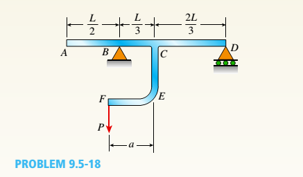
A beam ABCD consisting of a simple span BD and an overhang AB\s loaded by a force P acting at the end of the bracket CEF (see figure),
- Determine the deflection at the end of the over h a tig.

(a)
Deflection at A.
Answer to Problem 9.5.18P
The deflection at A is
Explanation of Solution
Given Information:
The following figure is given along with relevant information,
Calculation:
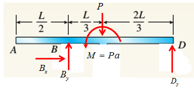
Consider the following diagram,

Transfer the load P from F to C and draw reaction forces as shown in following figure,

Take equilibrium of forces in horizontal direction as,
Take equilibrium of moments about D as,
Take equilibrium of forces in vertical direction as,
The bending moment at distance x from point A is given by,
The deflection and bending moment is related by following differential equation
Integrate differential equation (1) with respect to x by putting expression for M to get angle of rotations, as,
Integrate angle of rotation with respect to x get deflections as,
The following conditions are used to evaluate integration constants,
Then substitute values of constants and
Conclusion:
Therefore the deflection at A is
(b)
Condition for upward and downward deflection at A .
Answer to Problem 9.5.18P
The deflection at A is upward when
Explanation of Solution
Given Information:
The following figure is given along with relevant information,

Calculation:
Consider the following diagram,

Transfer the load P from F to C and draw reaction forces as shown in following figure,
Take equilibrium of forces in horizontal direction as,
Take equilibrium of moments about D as,
Take equilibrium of forces in vertical direction as,
The bending moment at distance x from point A is given by,
The deflection and bending moment is related by following differential equation
Integrate differential equation (1) with respect to x by putting expression for M to get angle of rotations, as,
Integrate angle of rotation with respect to x get deflections as,
The following conditions are used to evaluate integration constants,
Then substitute values of constants and
Now, the deflection at A is upward when
Conclusion:
Therefore the deflection at A is upward when
Want to see more full solutions like this?
Chapter 9 Solutions
Mechanics of Materials (MindTap Course List)


- A propped cantilever beam of length L = 54 in. with a sliding support supports a uniform load of intensity q (see figure). The beam is made of steel {<7y = 36 ksi) and has a rectangular cross section of width/) = 4.5 in. and height h = 6.0 in. What load intensity q will produce a fully plastic condition in the beam?arrow_forward-14 A simply supported composite beam with a 3.6 m span supports a triangularly distributed load of peak intensity q0at mid-span (see figure part a). The beam is constructed of two wood joists, each 50 mm x 280 mm, fastened to two steel plates, one of dimensions 6 mm × 80 mm and the lower plate of dimensions 6 mm x 120mm (see figure part b). The modulus of elasticity for the wood is 11 GPa and for the steel is 210 GPa. If the allowable stresses are 7 MPa for the wood and 120 MPa for the steel, find the allowable peak load intensity q0maxwhen the beam is bent about the z axis. Neglect the weight of the beam.arrow_forwardA steel beam ABC is simply supported at A and held by a high-strength steel wire at B (see figure). A load P = 240 lb acts at the free end C. The wire has axial rigidity EA = 1500 x 103 lb, and the beam has flexural rigidity EI = 36 X 106 lb-in". What is the deflectionarrow_forward
- The overhanging beam A BCD supports two concentrated loads P and Q (see figure), For what ratio PIQ will the deflection at point B be zero? For what ratio will the deflection at point D be zero? If Q is replaced by a uniform load with intensity q (on the overhang), repeat parts (a) and (b), but find ratio Pl(qa).arrow_forwardA uniformly loaded, steel wide-flange beam with simple supports (see figure) has a downward deflection of 10 mm at the midpoint and angles of rotation equal to 0.01 radians at the ends. Calculate the height h of the beam if the maximum bending stress is 90 MPa and the modulus of elasticity is 200 GPa, (Use the formulas of Example 9-L)arrow_forwardBeam ABC is fixed at support A and rests (at point B) upon the midpoint of beam DE (see part a of the figure). Thus, beam, ABC may be represented as a propped cantilever beam with an overhang BC and a linearly elastic support of stiffness k at point B (see part b of the figure). The distance from A to B is L = 10 ft, the distance from B to C is L/2 = 5 ft, and the length of beam DE is L = 10 ft. Both beams have the same flexural rigidity EI. A concentrated load P = 1700 lb acts at t lie free end of beam ABC. Determine the reactions RA, RB+ and MAfor beam ABC. Also, draw the shear-force and bending-moment diagrams for beam ABC, labeling all critical ordinates.arrow_forward
- A cantilever beam AB of length L = 6.5 ft supports a trapezoidal distributed load of peak intensity 4, and minimum intensity q/2tthat includes the weight of the beam (see figure). The beam is a steel W 12 × 14 wide-flange shape (see Table F-l(a), Appendix F). Calculate the maximum permissible load q based upon (a) an allowable bending stress eallow = 18 ksi and (b) an allowable shear stress eallow = 7,5 ksi. Note: Obtain the moment of inertia and section modulus of the beam from Table F-l(a).arrow_forwardA simply supported wooden I-beam with a 12-ft span supports a distributed load of intensity q = 90 lb/ft over its length (see figure part a). The beam is constructed with a web of Douglas-fir plywood and flanges of pine glued to the web, as shown in the figure part b. The plywood is 3/8 in. thick: the flanges are 2 in, × 2 in, (actual size). The modulus of elasticity for the plywood is 1,600,000 psi and for the pine is 1,200,000 psL Calculate the maximum bending stresses in the pine flanges and in the plywood web. What is q, if allowable stresses are 1600 psi in the flanges and 1200 psi in the web?arrow_forwardA simple beam that is 18 ft long supports a uniform load of intensity q. The beam is constructed of two C8 x 11.5 sections (channel sections or C-shapes) on either side of a 4 × 8 (actual dimensions) wood beam (see the cross section shown in the figure part a). The modulus of elasticity of the steel (E; = 30,000 ksi) is 20 times that of the wood (Ew). (a) If the allowable stresses in the steel and wood are 12,000 psi and 900 psi, respectively, what is the allowable load qmax Note: Disregard the weight of the beam, and see Table F-3(a) of Appendix F for the dimensions and properties of the C-shape beam. (b) If the beam is rotated 90° to bend about its v axis (see figure part b) and uniform load q = 250 lb/ft is applied, find the maximum stresses trs and crw in the steel and wood, respectively Include the weight of the beam. (Assume weight densities of 35 lb/ft3 and 490 lb/ft3 for the wood and steel, respectively.)arrow_forward
- A cantilever beam AB of length L = 6 It is constructed of a W 8 x 21 wide-flange section (see figure), A weight W = 1500 lb falls through a height h = 0.25 in. onto the end of the beam. Calculate the maximum deflection £m.iy of the end of the beam and the maximum bendini* stress *rm,vdue to the falling weight, (Assume E = 30 X 10 psi,)arrow_forwardA propped cantilever beam A BC (see figure) has a shear release just right of the mid-span. (a) Select the most economical wood beam from the table in Appendix G; assume4 = 55 lb/ft, L = 16 ft, o~aw= 1750 psi, and raw= 375 psi. Include the self-weight of the beam in your design. (b) If a C 10 x 25 steel beam is now used for beam ABC, what is the maximum permissible value of load variable q? Assume üi = 16 ksi and L = 10 ft. Include the self-weight of the beam in your analysis.arrow_forwardA simple beam of length L = 5 m carries a uniform load of intensity q = 5,8 kN/m and a concentrated load 22.5 kN (see figure). (a) Assuming tra]]ow = 110 MPa, calculate the required section modulus S. Then select the most economical wide-flange beam (W shape) from Table F-l(b) in Appendix F, and recalculate S, taking into account the weight of the beam. Select a new beam if necessary. (b) Repeat part (a), but now assume that the design requires that the W shape must be used in weak axis bending (i.e., it must bend about the 2-2 (or y) axis of the cross section).arrow_forward
 Mechanics of Materials (MindTap Course List)Mechanical EngineeringISBN:9781337093347Author:Barry J. Goodno, James M. GerePublisher:Cengage Learning