
Mechanics of Materials (MindTap Course List)
9th Edition
ISBN: 9781337093347
Author: Barry J. Goodno, James M. Gere
Publisher: Cengage Learning
expand_more
expand_more
format_list_bulleted
Concept explainers
Videos
Textbook Question
Chapter 9, Problem 9.5.24P
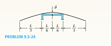
A thin metal strip of total weight W and length L is placed across the top of a flat table of width L2as shown in the figure.
What is the clearance S between the strip and the middle of the table? (The strip of metal has flexural rigidity EI.)
Expert Solution & Answer
Want to see the full answer?
Check out a sample textbook solution
Students have asked these similar questions
The plate shown in (Figure is supported by a roller and a cable in the x-direction at A, a ball-and-socket joint at B, and a roller at C. A force F = 8.1 kN is applied at the centroid of the plate parallel to the yz-plane and making an angle of θ = 40 ∘ with the xy-plane. The sides AB and BC of the plate have length L = 1.5 m .
1) What is the reaction force in the z-direction at point B?
2) What is the tension T in the cable?
3) What is the reaction force in the x-direction at point B? Let a positive force act in the positive x-direction.
The plate shown in Figure is supported by a roller and a cable in the x-direction at A, a ball-and-socket joint at B, and a roller at C. A force F = 8.1 kN is applied at the centroid of the plate parallel to the yz-plane and making an angle of θ = 40 ∘ with the xy-plane. The sides AB and BC of the plate have length L = 1.5 m .
1) What is the reaction force in the y-direction at point B? Let a positive force act in the positive y-direction?
2) What is the reaction force in the z-direction at point C?
3) What is the reaction force in the z-direction at point A?
Truss members supporting a roof are connectedto a 26-mm-thick gusset plate by a 22-mm diameterpin, as shown in the figure and photo. The two endplates on the truss members are each 14 mm thick.(a) If the load P = 80 kN, what is the largest bearingstress acting on the pin?(b) If the ultimate shear stress for the pin is190 MPa, what force Pult is required to cause thepin to fail in shear?Disregard friction between the plates.
Chapter 9 Solutions
Mechanics of Materials (MindTap Course List)
Ch. 9 - The equation of the deflection curve for a...Ch. 9 - The equation of the deflection curve for a simply...Ch. 9 - -3 The deflection curve for a simple beam AB (see...Ch. 9 - The deflection curve for a simple beam AB (sec...Ch. 9 - The deflection curve for a cantilever beam AB (sec...Ch. 9 - The deflection curve for a cantilever beam AB (see...Ch. 9 - A simply supported beam is loaded with a point...Ch. 9 - A I-meter-long, simply supported copper beam (E =...Ch. 9 - A wide-flange beam (W 12 x 35) supports a uniform...Ch. 9 - A uniformly loaded, steel wide-flange beam with...
Ch. 9 - What is the span length L of a uniformly loaded,...Ch. 9 - -6 Calculate the maximum deflection of a uniformly...Ch. 9 - A cantilever beam with a uniform load (see figure)...Ch. 9 - A gold-alloy microbeam attached to a silicon wafer...Ch. 9 - Obtain a formula for the ratio c/maxof the...Ch. 9 - A cantilever beam model is often used to represent...Ch. 9 - B cams AB and CDE are connected using rigid link...Ch. 9 - -12 Derive the equation of the deflection curve...Ch. 9 - -13 Derive the equation of the deflection curve...Ch. 9 - -14 A cantilever beam AB supporting a triangularly...Ch. 9 - A cantilever beam has a length L = 12 ft and a...Ch. 9 - A simple beam with an overhang is subjected to d...Ch. 9 - -17 A cantilever beam AB is acted upon by a...Ch. 9 - -18 The beam shown in the figure has a sliding...Ch. 9 - -19 Derive the equations of the deflect ion curve...Ch. 9 - -20 Derive the equations of the deflection curve...Ch. 9 - -21 Derive the equations of the deflection curve...Ch. 9 - -22 Derive the equations of the deflection curve...Ch. 9 - -23 The beam shown in the figure has a sliding...Ch. 9 - -1 Derive the equation of the deflection curve for...Ch. 9 - -2 A simple beam AB is subjected to a distrib uted...Ch. 9 - -3 The simple beam AB shown in the figure has...Ch. 9 - -4 A beam with a uniform load has a sliding...Ch. 9 - -5 The distributed load acting on a cantilever...Ch. 9 - -6 A cantilever beam .4B is subjected to a...Ch. 9 - -7 A beam on simple supports is subjected to a...Ch. 9 - Derive the equation of the deflection curve for...Ch. 9 - -9 Derive the equations of the deflection curve...Ch. 9 - -10 Derive the equations of the deflection curve...Ch. 9 - A simply supported beam (E = 1600 ksi) is loaded...Ch. 9 - A simply supported beam (E = 12 GPa) carries a...Ch. 9 - Copper beam AB has circular cross section with a...Ch. 9 - Beam ABC is loaded by a uniform load q and point...Ch. 9 - A cantilever beam of a length L = 2.5 ft has a...Ch. 9 - A cantilever beam carries a trapezoidal...Ch. 9 - -5-7 A cantilever beam AB carries three equalaly...Ch. 9 - A simple beam AB supports five equally spaced...Ch. 9 - The cantilever beam AB shown in the figure has an...Ch. 9 - Beam ACE hangs from two springs, as shown in the...Ch. 9 - What must be the equation y =f(x) of the axis of...Ch. 9 - -12 Determine the angle of rotation Band...Ch. 9 - The cantilever beam ACE shown in the figure has...Ch. 9 - A cantilever beam is subjected to load P at...Ch. 9 - Use the method of superposition to find the angles...Ch. 9 - Repeat Problem 9,5-15 for the anti-symmetric...Ch. 9 - A cantilever beam is subjected to a quadratic...Ch. 9 - A beam ABCD consisting of a simple span BD and an...Ch. 9 - A horizontal load P acts at end C of the bracket...Ch. 9 - A beam ABC having flexural rigidity EI = 75 kN irT...Ch. 9 - Determine the angle of rotation 0Band deflectionCh. 9 - -22 A simple beam AB supports a uniform load of...Ch. 9 - The overhanging beam A BCD supports two...Ch. 9 - A thin metal strip of total weight W and length L...Ch. 9 - An overhanging beam ABC with flexural rigidity EI...Ch. 9 - A beam A BCD rests on simple supports at B and C...Ch. 9 - The compound beam ABC shown in the figure has a...Ch. 9 - A compound beam ABC DE (see figure) consists of...Ch. 9 - A steel beam ABC is simply supported at A and held...Ch. 9 - -30. Calculate the deflection at point C of a beam...Ch. 9 - Compound beam ABC is loaded by point load P = 1.5...Ch. 9 - The compound beam shown in the figure consists of...Ch. 9 - -33 Find the horizontal deflection hand verti cal...Ch. 9 - The fr a me A BCD shown in the heure is squeezed...Ch. 9 - A framework A BCD is acted on by counterclockwise...Ch. 9 - A framework A BCD is acted on by force P at 2L/3...Ch. 9 - A beam ABCDE has simple supports at B and D and...Ch. 9 - A frame ABC is loaded at point C by a force P...Ch. 9 - The wing of a large commercial jet is represented...Ch. 9 - The wing of a small plane is represented by a...Ch. 9 - Find an expression for required moment MA(in terms...Ch. 9 - Find an expression for required moment MA(in terms...Ch. 9 - Find required distance d (in terms of L) so that...Ch. 9 - A cantilever beam has two triangular loads as...Ch. 9 - -1 A cantilever beam AB is subjected to a uniform...Ch. 9 - The load on a cantilever beam AB has a triangular...Ch. 9 - A cantilever beam AB is subjected to a...Ch. 9 - Determine the angle of rotation BBand the...Ch. 9 - -5 Calen1ate the deflections S 3a ndCh. 9 - A cantileverbeam^Cßsupportstwo concentrated loads...Ch. 9 - Obtain formulas for the angle of rotation 0Aat...Ch. 9 - A simple beam AB supports two concentrated loads P...Ch. 9 - A simple beam AB is subjected to a load in the...Ch. 9 - -10 The simple beam AB shown in the figure...Ch. 9 - A simple beam AB is subjected to couples M0and 2A0...Ch. 9 - The cantilever beam ACB shown in the figure has...Ch. 9 - The cantilever beam ACB shown in the figure...Ch. 9 - Beam ACB hangs from two springs, as shown in the...Ch. 9 - -4 A simple beam ABCD has moment of inertia I near...Ch. 9 - A beam ABC has a rigid segment from A to B and a...Ch. 9 - A simple beam ABC has a moment of inertia 1,5 from...Ch. 9 - The tapered cantilever beam AB shown in the figure...Ch. 9 - The tapered cantilever beam AB shown in the figure...Ch. 9 - A tapered cantilever beam A B supports a...Ch. 9 - A tapered cantilever beam AB supports a...Ch. 9 - Repeat Problem 97-10, but now use the tapered...Ch. 9 - A simple beam ACE is constructed with square cross...Ch. 9 - A uniformly loaded simple beam AB (see figure) of...Ch. 9 - A simple beam AB of length L supports a...Ch. 9 - A propped cantilever beam AB of length L and with...Ch. 9 - A simple beam AB of length L is subjected to loads...Ch. 9 - A beam ABC with simple supports at A and B and an...Ch. 9 - A simple beam ACB supporting a uniform load q over...Ch. 9 - The frame shown in the figure consists of a beam...Ch. 9 - A simple beam AB of length L is loaded at the...Ch. 9 - The simple beam shown in the figure supports a...Ch. 9 - An overhanging beam ABC supports a concentrated...Ch. 9 - The cantilever beam shown in the figure supports a...Ch. 9 - A simple beam ACB supports a uniform load of...Ch. 9 - A cantilever beam ACB supports two concentrated...Ch. 9 - The cantilever beam A CB shown in the hgure is...Ch. 9 - The frame A BC support s a concentrated load P at...Ch. 9 - A simple beam ABC DE supports a uniform load of...Ch. 9 - An overhanging beam ABC is subjected to a couple...Ch. 9 - An overhanging beam ABC rests on a simple support...Ch. 9 - A symmetric beam A BCD with overhangs at both ends...Ch. 9 - A heavy object of weight W is dropped onto the...Ch. 9 - An object of weight Wis dropped onto the midpoint...Ch. 9 - A cantilever beam AB of length L = 6 It is...Ch. 9 - A weight W = 20 kN falls through a height h = 1,0...Ch. 9 - A weight W = 4000 lb falls through a height h =...Ch. 9 - An overhanging beam ABC with a rectangular cross...Ch. 9 - A heavy flywheel rotates at an angular speed m...Ch. 9 - A simple beam AB of length L and height /;...Ch. 9 - A cantilever beam JA of length Land height/; (see...Ch. 9 - An overhanging beam ABC of height h has a sliding...Ch. 9 - A simple beam AB of length L and height h (see...Ch. 9 - Beam AB has an elastic support kR at A, pin...
Knowledge Booster


Learn more about
Need a deep-dive on the concept behind this application? Look no further. Learn more about this topic, mechanical-engineering and related others by exploring similar questions and additional content below.Similar questions
- A steel riser pipe hangs from a drill rig located offshore in deep water (see figure). (a) What is the greatest length (meters) it can have without breaking if the pipe is suspended in the air and the ultimate strength (or breaking strength) is 550 MPa? (b) If the same riser pipe hangs from a drill rig at sea, what is the greatest length? (Obtain the weight densities of steel and sea water from Table M, Appendix I. Neglect the effect of buoyant foam casings on the pipe.)arrow_forwardA large precast concrete panel for a warehouse is raised using two sets of cables at two lift lines, as shown in the figure part a. Cable 1 has a length L1 = 22 Ft, cable 2 has a length L2= 10 ft, and the distance along the panel between lift points Band D is d = 14 ft (see figure part b). The total weight of the panel is W = 85 kips. Assuming the cable lift Forces F at each lift line are about equal, use the simplified model of one half of the panel in figure part b to perform your analysis for the lift position shown. Find the required cross-sectional area AC of the cable if its breaking stress is 91 ksi and a factor of safety of 4 with respect to failure is desired.arrow_forwardA cylindrical brick chimney of height H weighs w = 825 lb/ft of height (see figure). The inner and outer diameters are d1= 3 ft and d2= 4 ft, respectively. The wind pressure against the side of the chimney is p = 10 lb/ft2 of projected area. Determine the maximum height H if there is to be no tension in the brickwork.arrow_forward
- A retaining wall 6 ft high is constructed of horizontal wood planks 2.5 in. thick (actual dimension) that are supported by vertical wood piles of a 12 in, diameter (actual dimension), as shown in the figure. The lateral earth pressure is pt=125 lb/ft2 at the top of the wall and p2= 425 lb/ft2 at the bottom. Assuming that the allowable stress in the wood is 1175 psi, calculate the maximum permissible spacing s of the piles. Find the required diameter of the wood piles so that piles and planks (f = 2.5 in.) reach the allowable stress at the same time. Hint: Observe that the spacing of the piles may be governed by the load-carrying capacity of either the planks or the piles. Consider the piles to act as cantilever beams subjected to a trapezoidal distribution of load, and consider the planks to act as simple beams between the piles. To be on the safe side, assume that the pressure on the bottom plank is uniform and equal to the maximum pressure.arrow_forwardA plane truss is subjected to loads 2P and P at joints B and C, respectively, as shown in the figure part a. The truss bars are made of two L 102 X 76 X 6.4 steel angles (see Table F-5(b): cross-sectional area or the two angles, A = 2180 mm2, and figure part b) having an ultimate stress in tension equal to 390 MPa. The angles are connected to a 12-mm-thick gusset plate at C(figure part c) with 16-mm diameter rivets; assume each rivet transfers an equal share of the member force to the gusset plate. The ultimate stresses in shear and bearing for the rivet steel are 190 MPa and 550 MPa, respectively. Determine the allowable load Pallowif a safety factor of 2.5 is desired with respect to the ultimate load that can be carried. Consider tension in the bars, shear in the rivets, bearing between the rivets and gusset plate. Disregard friction between the plates the bars, and also bearing between the rivets and the and the weight of the truss itself.arrow_forwardTruss members supporting a roof are connected to a 26-mm-thick gusset plate by a 22-mm diameter pin, as shown in the figure and photo. The two end plates on the truss members are each 14 mm thick. (a) If the load P = 80 kN, what is the largest bearing stress acting on the pin? (b) If the ultimate shear stress for the pin is 190 MPa, what force Pult is required to cause the pin to fail in shear? Disregard friction between the plates.arrow_forward
- A steel post (E=30×106) having thickness t = 1/8 in. and height L = 72 in. support a stop sign (see figure), where s = 12.5 in. The height of the post L is measured from the base to the centroid of the sign. The stop sign is subjected to wind pressure p = 20 lb/ft2 normal to its surface. Assume that the post is fixed at its base. What is the resultant load on the sign? (Sec Appendix E, Case 25, for properties of an octagon, n =8.) What is the maximum bending stress in the post? Repeat part (b) if the circular cut-outs arc eliminated over the height of the post.arrow_forwardBy what distance h does the cage shown in the figure move downward when the weight W is placed inside it? (See the figure.) Consider only the effects of the stretching of the cable, which has axial rigidity EA = 10,700 kN. The pulley at A has a diameter da= 300 mm and the pulley at B has a diameter dB= 150 mm. Also, the distance L1= 4.6 m, the distance L2=10.5 m, and the weight W = 22 kN. Note: When calculating the length of the cable. include the parts of the cable that go around the pulley sat A and B.arrow_forwardA long re Lai nine: wall is braced by wood shores set at an angle of 30° and supported by concrete thrust blocks, as shown in the first part of the figure. The shores are evenly spaced at 3 m apart. For analysis purposes, the wall and shores are idealized as shown in the second part of the figure. Note that the base of the wall and both ends of the shores are assumed to be pinned. The pressure of the soil against the wall is assumed to be triangularly distributed, and the resultant force acting on a 3-meter length of the walls is F = 190 kN. If each shore has a 150 mm X 150 mm square cross section, what is the compressive stressarrow_forward
- The truss ABC shown in the figure supports a vertical load W at joint B. Each member is a slender circular steel pipe (E = 30,000 ksi) with an outside diameter of 4 in. and wall thickness 0.25 in. The distance between supports is 23 ft. Joint B is restrained against displacement perpendicular to the plane of the truss. Determine the critical value Wcr of the load.arrow_forwardA cylinder filled with oil is under pressure from a piston, as shown in the figure. The diameter d of the piston is 1,80 in. and the compressive force F is 3500 lb. The maximum allowable shear stress t^^, in the wall of the cylinder is 5500 psi. What is the minimum permissible thickness t„± of the cylinder wall? (Sec figurearrow_forwardA hollow circular pipe (see figure} support s a load P that is uniformly distributed around a cap plate at the top of the lower pipe. The inner and outer diameters of the upper and lower parts of the pipe are d1= 50 mm, d2= 60 mm, rf3 = 57 mm, and d1= 64 mm, respectively. Pipe lengths are Lt= 2 m and L, = 3 m. Neglect the self-weight of the pipes. Assume that cap plate thickness is small compared to I, and E,. Let E = 110 MPa. (a) If the tensile stress in the upper part is d = 10.5 MPa. what is load PI Also, what are reactions ft, at the upper support and R-, at the lower support? What is the stress ar(MPa) in the lower part? (b) Find displacement S(mm) at the cap plate. Plot the axial force diagram (AFD) [Ar(.f)] and axial displacement diagram (ADD)[5(.t)]. (c) Add the uniformly distributed load q along the censorial axis of pipe segment 2. Find q (kN/m) so that It, = 0. Assume that load P from part (a) is also applied.arrow_forward
arrow_back_ios
SEE MORE QUESTIONS
arrow_forward_ios
Recommended textbooks for you
 Mechanics of Materials (MindTap Course List)Mechanical EngineeringISBN:9781337093347Author:Barry J. Goodno, James M. GerePublisher:Cengage Learning
Mechanics of Materials (MindTap Course List)
Mechanical Engineering
ISBN:9781337093347
Author:Barry J. Goodno, James M. Gere
Publisher:Cengage Learning
EVERYTHING on Axial Loading Normal Stress in 10 MINUTES - Mechanics of Materials; Author: Less Boring Lectures;https://www.youtube.com/watch?v=jQ-fNqZWrNg;License: Standard YouTube License, CC-BY