
Concept explainers
Videos
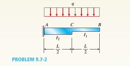
The cantilever beam ACB shown in the figure supports a uniform load of intensity q throughout its length. The beam has moments of inertia I2and IYin parts AC and CB, respectively.
- Using the method of superposition, determine the deflection SBat the free end due to the uniform load.
a.
The deflectiony13
Answer to Problem 9.7.2P
The deflectiony1313
Explanation of Solution
Given:
We have the data,
Length of the beam ACB as, L
Intensity of uniform load, q
Moment of inertia of,
Moment of inertia of,
Concept Used:
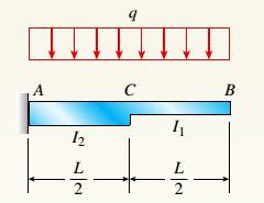
The cantilever beam ACB as per the below figure supports a uniform load of intensity q throughout its length with moments of inertia

Calculation:
We have the below diagram for part CB as below.
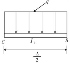
Deflection at point B would be calculated as,
We have the below diagram for part AC as below.
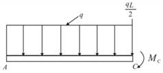
The moment at point C,
The deflection at point C can be calculated as below.
Angle of rotation at point C can be determined as,
At point B, the deflection would be,
Therefore, the total deflection at point B would be,
Conclusion:
The deflection
b.
The ratio r of the deflection
Answer to Problem 9.7.2P
The ratio r is
Explanation of Solution
Given:
We have the data,
Length of the beam, L
Moment of inertia of,
Moment of inertia of,
Load at point B, P
Concept Used:
The cantilever beam ACB as per the below figure supports a uniform load of intensity q throughout its length with moments of inertia
Calculation:
For the prismatic cantilever beam, we have
We can calculate the ratio as below.
Conclusion:
The ratio r is calculated using the cantilever beam concept and moment diagram.
c.
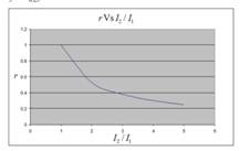
To plot : A graph for the deflection ratio (r) versus the ratio
Explanation of Solution
Given:
We have the data,
Length of the beam, L
Moment of inertia of,
Moment of inertia of,
Load at point B, P
Concept Used:
The cantilever beam ACB as per the below figure supports a uniform load of intensity q throughout its length with moments of inertia

Calculation:
The values for plotting graph are shown in below table:
| r | |
| 1 | 1 |
| 2 | 0.53 |
| 3 | 0.38 |
| 4 | 0.3 |
| 5 | 0.25 |
We will get graph as shown below:

Conclusion:
The graph for the deflection ratio (r) versus the ratio
Want to see more full solutions like this?
Chapter 9 Solutions
Mechanics of Materials (MindTap Course List)


- -20 Derive the equations of the deflection curve for a cantilever beam AB carrying a uniform load of intensity q over part of the span (see figure). Also, determine the deflection Bat the end of the beam. Use the second-order differential equation of the deflection curve.arrow_forward-21 Derive the equations of the deflection curve for a cantilever beam AB supporting a distributed load of peak intensity q0acting over one-half of the length (see figure). Also, obtain formulas for the deflections Band cat points B and C, respectively Use the second-order differentia] equation of the deflection curve.arrow_forwardThe cantilever beam ACB shown in the figure has moments of inertia /, and I{in parts AC and CB, respectively. Using the method of superposition, determine the deflection 8Bat the free end due to the load P. Determine the ratio r of the deflection 8Bto the deflection S:at the free end of a prismatic cantilever with moment of inertia /] carrying the same load. Plot a graph of the deflection ratio r versus the ratio 12 //L of the moments of inertia. (Let /, II- vary from I to 5.)arrow_forward
- -12 Derive the equation of the deflection curve for a cantilever beam AB supporting a load P at the free end (see figure). Also, determine the deflection Band angle of rotation bat the free end. Use the second-order differential equation of the deflection curve.arrow_forwardA simply supported beam (E = 1600 ksi) is loaded by a triangular distributed load from A to C(see figure). The load has a peak intensity q0= 10 lb/ ft, and the deflection is known to be 0.01 in, at point C. The length of the beam is 12 ft, and the ratio of the height to the width of the cross section is (h:b) 2:1, Find the height h; and width h of the cross section of the beam.arrow_forwardA cantilever beam has a length L = 12 ft and a rectangular cross section (b = 16 in., h = 24 in.), A linearly varying distributed load with peak intensity q0acts on the beam, (a) Find peak intensity q0if the deflection at joint B is known to be 0.18 in. Assume that modulus E = 30,000 ksi. (b) Find the location and magnitude of the maximum rotation of the beam.arrow_forward
- Beam ACB hangs from two springs, as shown in the figure. The springs have stiffnesses Jt(and k2^ and the beam has flexural rigidity EI. What is the downward displacement of point C, which is at the midpoint of the beam, when the moment MQis applied? Data for the structure are M0 = 7.5 kip-ft, L = 6 ft, EI = 520 kip-ft2, kx= 17 kip/ft, and As = 11 kip/ft. Repeat part (a), but remove Af0 and instead apply uniform load q over the entire beam.arrow_forward-13 Derive the equation of the deflection curve for a simple beam AB loaded by a couple M0at the left-hand support (see figure). Also, determine the maximum deflection max Use the second-order differential equation of the deflection curve.arrow_forwardA simple beam ABC has a moment of inertia 1,5 from A to B and A from B to C (see figure). A concentrated load P acts at point B. Obtain the equations of the deflection curves for both parts of the beam. From the equations, determine the angles of rotation 0Aand Bcat the supports and the deflection 6Bat point B.arrow_forward
- Compound beam ABC is loaded by point load P = 1.5 kips at distance 2aB from point A and a triangularly distributed load on segment BC with peak intensity qü= 0.5 kips/ft. If length a = 5 ft and length/) = 10 ft, find the deflection at B and rotation at A. Assume that £ = 29,000 ksi and / = 53.8 in4.arrow_forward-14 A cantilever beam AB supporting a triangularly distributed load of maximum intensity q0is shown in the figure. Derive the equation of the deflection curve and then obtain formulas for the deflection Band angle of rotation Bat the free end. Use the second-order differential equation of the deflection curve.arrow_forward-17 A cantilever beam AB is acted upon by a uniformly distributed moment (bending moment, not torque) of intensity m per unit distance along the axis of the beam (see figure). Derive the equation of the deflection curve and then obtain formulas for the deflection Band angle of rotation Bat the free end. Use the second-order differential equation of the deflection curve.arrow_forward
 Mechanics of Materials (MindTap Course List)Mechanical EngineeringISBN:9781337093347Author:Barry J. Goodno, James M. GerePublisher:Cengage Learning