
Videos
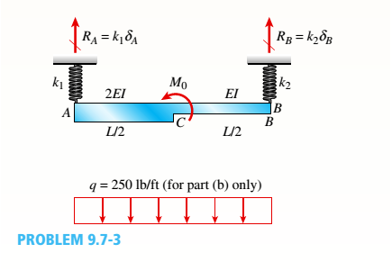
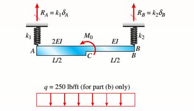
Beam ACB hangs from two springs, as shown in the figure. The springs have stiffnesses Jt(and k2^ and the beam has flexural rigidity EI.
- What is the downward displacement of point C, which is at the midpoint of the beam, when the moment MQis applied? Data for the structure are M0 = 7.5 kip-ft, L = 6 ft, EI = 520 kip-ft2, kx= 17 kip/ft, and As = 11 kip/ft.
- Repeat part (a), but remove Af0 and instead apply uniform load q over the entire beam.
a.
The downward displacement of point C of the beam.
Answer to Problem 9.7.3P
The downward displacement of point C is
Explanation of Solution
Given:
We have the data,
Concept Used:
Beam ACB hangs fro two springs which have stifness
Calculation:
We can write bending moment equations −moment at Point C as follows:
To determine slope equation, we are integrating the above equation, we will get,
To determine deflection equation, we are integrating the above equation, we will get,
Now applying the boundary conditions to find out the constants as follows:
To determine slope equation, we are integrating the above equation, we will get,
To determine deflection equation, we are integrating the above equation, we will get,
Now applying the boundary conditions to find out the constants as follows:
Now we will get the below values after solving equations (1), (2) and (3).
In deflection equation, we are putting values of
Once again in deflection equation, putting values of
Now calculating, the reactions at supports:
We can determine deflection at point A below.
We can determine deflection at point B below.
We can determine deflection at point C as below.
Therefore, we have determined the downward displacement of point C is
Conclusion:
The downward displacement of point C is calculated using deflection equation.
b.
The downward displacement of point C of the beam.
Answer to Problem 9.7.3P
The downward displacement of point C is
Explanation of Solution
Given:
We have the data,
Concept Used:
Beam ACB hangs fro two springs which have stifness

Calculation:
We can write bending moment equations −with uniform load q at Point C as follows:
To determine slope equation, we are integrating the above equation, we will get,
To determine deflection equation, we are integrating the above equation, we will get,
Now applying the boundary conditions to find out the constants as follows:
To determine slope equation, we are integrating the above equation, we will get,
To determine deflection equation, we are integrating the above equation, we will get,
Now applying the boundary conditions to find out the constants as follows:
Now we will get the below values after solving equations (4), (5) and (6).
In deflection equation, we are putting values of
Once again in deflection equation, putting values of
Now calculating, the reactions at supports:
We can determine deflection at point A as below.
We can determine deflection at point B below.
We can determine deflection at point C below.
Therefore, we have determined the downward displacement of point C is
Conclusion:
The downward displacement of point C is calculated by this formula :
Want to see more full solutions like this?
Chapter 9 Solutions
Mechanics of Materials (MindTap Course List)


- A propped cantilever beam of length L = 54 in. with a sliding support supports a uniform load of intensity q (see figure). The beam is made of steel {<7y = 36 ksi) and has a rectangular cross section of width/) = 4.5 in. and height h = 6.0 in. What load intensity q will produce a fully plastic condition in the beam?arrow_forwardThe hollow box beam shown in the figure is subjected to a bending moment M of such magnitude that the flanges yield but the webs remain linearly elastic. (a) Calculate the magnitude of the moment M if the dimensions of the cross section are A = 15 in., A] = 12.75 in., h = 9 in., and ey =7.5 in. Also, the yield stress is eY = 33 ksi. (b) What percent of the moment M is produced by the elastic core?arrow_forwardA singly symmetric beam with a T-section (see figure) has cross-sectional dimensions b = 140 mm, a = 190, 8 mm, b. = 6,99 mm, and fc = 11,2 mm. Calculate the plastic modulus Z and the shape factor.arrow_forward
- A simple beam of length L = 5 m carries a uniform load of intensity q = 5,8 kN/m and a concentrated load 22.5 kN (see figure). (a) Assuming tra]]ow = 110 MPa, calculate the required section modulus S. Then select the most economical wide-flange beam (W shape) from Table F-l(b) in Appendix F, and recalculate S, taking into account the weight of the beam. Select a new beam if necessary. (b) Repeat part (a), but now assume that the design requires that the W shape must be used in weak axis bending (i.e., it must bend about the 2-2 (or y) axis of the cross section).arrow_forwardA propped cantilever beam A BC (see figure) has a shear release just right of the mid-span. (a) Select the most economical wood beam from the table in Appendix G; assume4 = 55 lb/ft, L = 16 ft, o~aw= 1750 psi, and raw= 375 psi. Include the self-weight of the beam in your design. (b) If a C 10 x 25 steel beam is now used for beam ABC, what is the maximum permissible value of load variable q? Assume üi = 16 ksi and L = 10 ft. Include the self-weight of the beam in your analysis.arrow_forwardA cantilever beam AB of length L = 6.5 ft supports a trapezoidal distributed load of peak intensity 4, and minimum intensity q/2tthat includes the weight of the beam (see figure). The beam is a steel W 12 × 14 wide-flange shape (see Table F-l(a), Appendix F). Calculate the maximum permissible load q based upon (a) an allowable bending stress eallow = 18 ksi and (b) an allowable shear stress eallow = 7,5 ksi. Note: Obtain the moment of inertia and section modulus of the beam from Table F-l(a).arrow_forward
- A reinforced concrete T-beam (see figure) is acted on by a positive bending moment of M = 175 kip-ft. Steel reinforcement consists of four bars of 1.41-inch diameter. The modulus of elasticity for the concrete is Ec= 3000 ksi while that of the steel is £s = 29,000 ksi. Let b = 48 im, rf = 4 in., bw=15 in,, and d = 24 in, Find the maximum stresses in steel and concrete, If allowable stresses for concrete and steel are o"ac = 1400 psi and tr^ =18 ksi, respectively, what is the maximum permissible positive bending moment?arrow_forwardA hollow box beam with height h = 16 in,, width h = 8 in,, and constant wall thickness r = 0.75 LiL is shown in the figure. The beam is constructed of steel with yield stress ty = 32 ksi. Determine the yield moment My, plastic moment A/p, and shape factor.arrow_forwardBeam ACE hangs from two springs, as shown in the figure. The springs have stiffnesses kxand k2and the beam has flex lira I rigidity EL (a) What is the downward displacement of point C, which is at the midpoint of the beam, when the moment M0 is applied? Data for the structure are as follows: M0= 10,0 kN m, L = 1.8 m, EI = 216 kN m2, Jt, = 250 kN/m, and k2= 160 kN/m, (b) Repeat part (a), but remove A/() and apply a uniform load q — 3.5 kN/m to the entire beam.arrow_forward
- A simple beam that is 18 ft long supports a uniform load of intensity q. The beam is constructed of two C8 x 11.5 sections (channel sections or C-shapes) on either side of a 4 × 8 (actual dimensions) wood beam (see the cross section shown in the figure part a). The modulus of elasticity of the steel (E; = 30,000 ksi) is 20 times that of the wood (Ew). (a) If the allowable stresses in the steel and wood are 12,000 psi and 900 psi, respectively, what is the allowable load qmax Note: Disregard the weight of the beam, and see Table F-3(a) of Appendix F for the dimensions and properties of the C-shape beam. (b) If the beam is rotated 90° to bend about its v axis (see figure part b) and uniform load q = 250 lb/ft is applied, find the maximum stresses trs and crw in the steel and wood, respectively Include the weight of the beam. (Assume weight densities of 35 lb/ft3 and 490 lb/ft3 for the wood and steel, respectively.)arrow_forwardA fixed-end beam AB carries point load P acting at point C. The beam has a rectangular cross section (b = 75 mm, h = 150 mm). Calculate the reactions of the beam and the displacement at point C. Assume that E = 190 GPa.arrow_forwardBeam AB has an elastic support kR at A, pin support at B, length L, height h (see figure), and is heated in such a manner that the temperature difference T2T1 between the bottom and top of the beam is proportional to the distance from support A. Assume the temperature difference varies linearly along the beam: T2T1=T0x in which T0 is a constant having units of temperature (degrees) per unit distance. Assume the spring at A is unaffected by the temperature change. Determine the maximum deflection max of the beam, Repeat for a quadratic temperature variation along the beam, so T2T1=T0x2 What is max for parts (a) and (b) if kR goes to infinity?arrow_forward
 Mechanics of Materials (MindTap Course List)Mechanical EngineeringISBN:9781337093347Author:Barry J. Goodno, James M. GerePublisher:Cengage Learning