
Concept explainers
Videos
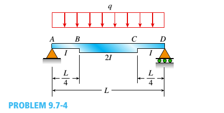
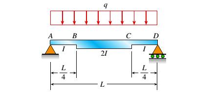
-4 A simple beam ABCD has moment of inertia I near the supports and moment of iertia 2I in the middle region, as shown in the figure. A uniform load of intensity q acts over the entire length of the beam.
Determine the quations of the deflection curve for the left-hand half of the beam. Also, find the angle of rotation
The equations of the deflection curve for the left-hand half of the beam, the angle of rotation
Answer to Problem 9.7.4P
The equations of the deflection curve for the left-hand half of the beam, the angle of rotation
Explanation of Solution
Given Information:
We have the simple beam ABCD with moment of inertia I near supports and moment of inertia 2I in the middle region as per below figure:
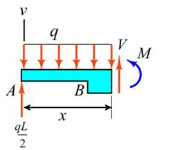
For the given simple beam below is the free body diagram.
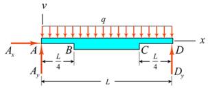
For the above diagram, applying the force equilibrium in horizontal direction, we will get,
At the point A, we are applying moment equilibrium,
Again we are applying the force equilibrium but in vertical direction,
Now we are taking a section which is at distance of x from point A where
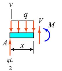
In above section, we are applying moment equilibrium,
We can get the slope equation after integrating the above equation.
Once again taking integration on both sides, we can determine the deflection equation,
Now we are taking a section which is at distance of x from point A where
In above section, we are applying moment equilibrium,
We can get the slope equation after integrating the above equation.
Once again taking integration on both sides, we can determine the deflection equation,
The exaggerated elastic curve for the simple beam ABCD can be represented as below diagram:
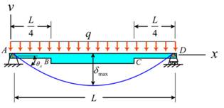
The boundary condition is applied for deflection equation for
This concludes that the slope contains value as zero when the maximum deflection of the beam
Now applying boundary condition to deflection equation
We are applying the continuity of slope condition at point B by evaluating the slope equations for segments
Now we are applying the continuity of deflection condition at point B by evaluating the slope equations for segments
For determination of deflection equation at segment
For determination of deflection equation at segment
For angle of rotation at point A using a slope equation for segment
Finally, the deflection at midpoint of the beam considering the deflection equation for segment
Conclusion:
The equations of the deflection curve for the left-hand half of the beam, the angle of rotation
Want to see more full solutions like this?
Chapter 9 Solutions
Mechanics of Materials (MindTap Course List)


- -9 Derive the equations of the deflection curve for beam ABC with sliding support at A and roller support at B, supporting a uniform load of intensity q acting on the overhang portion of the beam (see figure). Also, determine deflection cand angle of rotation c. Use the fourth-order differential equation of the deflection curve (the load equation).arrow_forward-20 Derive the equations of the deflection curve for a cantilever beam AB carrying a uniform load of intensity q over part of the span (see figure). Also, determine the deflection Bat the end of the beam. Use the second-order differential equation of the deflection curve.arrow_forwardThe beam AB shown in the figure is simply supported at A and B and supported on a spring of stiffness k at its midpoint C. The beam has flexural rigidity EI and length IL. What should be the stiffness k of the spring in order that the maximum bending moment in the beam (due to the uniform load) will have the smallest possible value?arrow_forward
- A simple beam ABC has a moment of inertia 1,5 from A to B and A from B to C (see figure). A concentrated load P acts at point B. Obtain the equations of the deflection curves for both parts of the beam. From the equations, determine the angles of rotation 0Aand Bcat the supports and the deflection 6Bat point B.arrow_forward-12 Derive the equation of the deflection curve for a cantilever beam AB supporting a load P at the free end (see figure). Also, determine the deflection Band angle of rotation bat the free end. Use the second-order differential equation of the deflection curve.arrow_forward-21 Derive the equations of the deflection curve for a cantilever beam AB supporting a distributed load of peak intensity q0acting over one-half of the length (see figure). Also, obtain formulas for the deflections Band cat points B and C, respectively Use the second-order differentia] equation of the deflection curve.arrow_forward
- -10 Derive the equations of the deflection curve for beam AB with sliding support at A and roller support at B, supporting a distributed load of maximum intensity q0acting on the right-hand half of the beam (see figure). Also, determine deflection A, angle of rotation B , and deflection cat the midpoint. Use the fourth-order differential equation of the deflection curve (the load equation).arrow_forward-17 A cantilever beam AB is acted upon by a uniformly distributed moment (bending moment, not torque) of intensity m per unit distance along the axis of the beam (see figure). Derive the equation of the deflection curve and then obtain formulas for the deflection Band angle of rotation Bat the free end. Use the second-order differential equation of the deflection curve.arrow_forwardA fixed-end beam AB of a length L is subjected to a uniform load of intensity q acting over the middle region of the beam (sec figure). Obtain a formula for the fixed-end moments MAand MBin terms of the load q, the length L, and the length h of the loaded part of the beam. Plot a graph of the fixed-end moment MAversus the length b of the loaded part of the beam. For convenience, plot the graph in the following nondimensional form: MAqL2/l2versusbL with the ratio b/L varying between its extreme values of 0 and 1. (c) For the special case in which ù = h = L/3, draw the shear-force and bending-moment diagrams for the beam, labeling all critical ordinates.arrow_forward
- A beam rests on supports at A and B and is loaded by a distributed load with intensity q as shown. A small gap exists between the unloaded beam and the support at C. Assume that span length L = 40 in. and flexural rigidity of the beam EI = 04 x 109lb-in2. Plot a graph of the bending moment at B as a function of the load intensity q. Hint: See Example 9-9 for guidance on computing the deflection at C.arrow_forwardThe wing of a large commercial jet is represented by a simplified prismatic cantilever beam model with uniform load \v and concentrated loads P at the two engine locations (see figure). Find expressions for the tip deflection and rotation at D in terms of \\\ P, L, and EL.arrow_forward-23 The beam shown in the figure has a sliding support at A and a roller support at B. The sliding support permits vertical movement but no rotation. Derive the equation of the deflection curve and determine the deflection Aat end A and also cat point C due to the uniform load of intensity q = P/ L applied over segment CB and load P at x = L / 3. Use the second-order differential equation of the deflection curve.arrow_forward
 Mechanics of Materials (MindTap Course List)Mechanical EngineeringISBN:9781337093347Author:Barry J. Goodno, James M. GerePublisher:Cengage Learning