
Concept explainers
(a)
To select the
Answer to Problem 9.8.7P
The beam
Explanation of Solution
Given:
Thickness of slab, t = 5.0 inches, spacing = 7.0 ft, span length, L = 30 feet, yield stress = 50 Ksi
Construction load = 20 psf, and live load = 800 psf.
The value of
Calculation:
Using LRFD method, we select a suitable shape that will satisfy the given conditions:
Calculate the loads on the beam as follows:
After curing we have,
Where,
between two adjacent beams.
The dead load on the beam after the concrete has cured is:
Calculate the live load on the beam using the following equation:
Where,
Calculate the factored uniformly distributed load after curing has completed by following formula:
Where,
Substitute the values, we get
Calculate the bending moment on the beam;
Where,
Try for
| DesignationImperial (in x lb/ft) | Depthh (in) | Widthw (in) | Web Thicknesstw (in) | Flange Thicknesstf (in) | Sectional Area (in2) | Weight (lbf/ft) | Static Parameters | |||
| Moment of Inertia | Elastic Section Modulus | |||||||||
| Ix (in4) | Iy (in4) | Sx (in3) | Sy (in3) | |||||||
| W 24 x 76 | 23.9 | 9 | 0.440 | 0.680 | 22.4 | 76 | 2100 | 82.5 | 176 | 18.4 |
Calculate the distance of the plastic neutral axis from the top of the slab as follows:
Where, b is the width of the concrete slab, t is the thickness of the concrete beam,
The effective flange width is as follows;
Substitute the values, we have
Compute the value of Y as shown below:
From the manual the value of nominal flexural strength of the beam
Comparing the values of
Thus, the beam is satisfactory excluding its self-weight.
Now for including the weight of the beam, we have
Calculate the factored uniformly distributed load after curing has completed by following formula:
Where,
Substitute the values, we get
Calculate the maximum bending moment on the beam;
Where,
Check the flexural strength of the beam including its weight.
Thus, the beam is satisfactory including its self-weight.
Check for the shear:
Checking the value of nominal value of shear strength of
Where,
The maximum shear force is as following for the above conditions:
Substitute the values, we have
Now comparing the two we have
Therefore, the beam is safe in shear and we can use
Calculate the factored uniformly distributed load before curing has completed by following formula:
Where,
Where,
between two adjacent beams.
The dead load on the beam before the concrete has cured is:
Calculate the live load on the beam using the following equation:
Where,
Substitute the values, we get
Calculate the maximum bending moment on the beam;
Where,
Check for the value of nominal flexural strength, the flexural strength of the beam before curing is
Comparing the values of
Therefore, the beam is satisfactory before the curing has completed.
Now calculating the maximum allowable live load deflection from the given beam using the formula as:
Substitute the values, we have
We have the value of lower bound moment of inertia for the given condition as follows:
Calculating the total load on the beam using the following :
Where,
Now by comparing the values, we have
Conclusion:
Hence, the beam
(b)
Use ASD method to select the
Answer to Problem 9.8.7P
The beam
Explanation of Solution
Calculation:
Now, we will use allowable stress design
Calculate the loads on the beam as follows:
After curing we have,
Where,
between two adjacent beams.
The dead load on the beam after the concrete has cured is:
Calculate the live load on the beam using the following equation:
Where,
Calculate the allowable uniformly distributed load after curing has completed by following formula:
Where,
Substitute the values, we get
Calculate the bending moment on the beam;
Where,
Compute the value of Y, which is the distance from the top of steel shape to compressive force
in concrete and is shown below:
Try for
Calculate the distance of the plastic neutral axis from the top of the slab as follows:
Where, b is the width of the concrete slab, t is the thickness of the concrete beam,
The effective flange width is as follows;
Substitute the values, we have
Compute the value of Y as shown below:
From the table 3-19 of the ASIC manual:
Trying for
Check whether the section is safe in flexure if the self -weight is excluded
Where,
Now comparing the values of
Substitute the values, we have
Therefore, the section is safe in flexure if the self -weight is excluded.
Let’s check for the beam weight :
Calculation of the maximum bending moment as follows:
Substitute the values, we get
Now check for the flexural strength including the beam weight:
Comparing the values of maximum bending moment and the nominal flexural strength as follows:
Therefore, the section is safe in flexure including the self-weight of the beam.
Check for the shear:
Checking the value of nominal value of shear strength of
Where,
The maximum shear force is as following for the above conditions:
Substitute the values, we have
Now comparing the two we have
Therefore, the beam is safe in shear and we can use
Calculate the loads on the beam as follows:
Before curing we have,
Where,
between two adjacent beams.
The dead load on the beam before the concrete has cured is:
Calculate the live load on the beam using the following equation:
Where,
Substitute the values, we get
Calculate the maximum bending moment on the beam;
Where,
Checking the value of nominal flexural strength of W- section from the ZX table of the ASIC manual:
Check whether the section is safe in flexure if the self -weight is excluded
Where,
Now comparing the values of
Substitute the values, we have
Therefore, the section is safe in before the curing of concrete.
Now calculating the maximum allowable live load deflection from the given beam using the formula as:
Substitute the values, we have
We have the value of lower bound moment of inertia for the given condition as follows:
Calculating the total load on the beam using the following :
Where,
Now by comparing the values, we have
Conclusion:
Hence, the beam
(c)
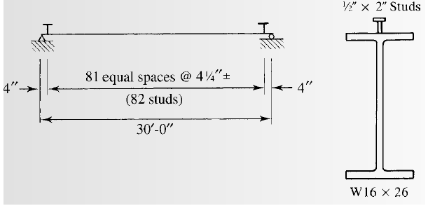
Selecting the stud anchors.
Answer to Problem 9.8.7P
We will use
Explanation of Solution
Calculation:
From AISC specifications, compute the maximum stud diameter using the equation:
Where,
Substitute the values, we get
Try for the studs of size
From table 3-21 for lightweight concrete take one stud at each of the beam position.
The number of studs for half beam can be found as follows:
Substitute the values, we have
Compute the number of studs as follows:
Substitute the value of
Calculate the spacing of the studs as follows:
Compute the minimum longitudinal spacing for studs using the equation
Where,
Substitute the values
Compute the minimum transverse spacing for studs using the equation
Where,
Substitute the values
Compute the maximum longitudinal spacing for studs using the equation
Where,
Substitute the values
But the upper limit of the spacing is 36 inches.
Calculate the require spacing for one stud at each of the section:
Substitute the values, we have
Conclusion:
Therefore, we will use
Want to see more full solutions like this?
Chapter 9 Solutions
Steel Design (Activate Learning with these NEW titles from Engineering!)


- Note For Problems 9.6-1 through 9.6-5, use the lower-bound moment of inertia for deflection of the composite section. Compute this as illustrated in Example 9.7. 9.6-2 Compute the following deflections for the beam in Problem 9.2-2. a. Maximum deflection before the concrete has cured. b. Maximum total deflection after composite behavior has been attained.arrow_forwardNote For Problems 9.6-1 through 9.6-5, use the lower-bound moment of inertia for deflection of the composite section. Compute this as illustrated in Example 9.7. 9.6-1 Compute the following deflections for the beam in Problem 9.2-1. a. Maximum deflection before the concrete has cured. b. Maximum total deflection after composite behavior has been attained.arrow_forwardAT-Beam has the following properties: bf = 750 mm, bw = 275 mm, d 560 mm, t = 115 mm. Concrete compressive strength fe 21 MPa and steel yield strength fy 415 MPa. T-Beam is under factored moment load of 720 kN-m. Locate the compression block under balanced condition from the extreme compression fiber.arrow_forward
- Q. Composite beam.arrow_forwardA rectangular beam of width 375 mm is reinforced with 3-32 mm bars at the bottom in a single layer. The centroid of these bars is 550 mm from extreme compression fiber. Use f’c = 27 MPa, fy = 420 MPa, NSCP 2015 provisions, and the DERIVED EQUATION Method. Calculate the Design Strength of the beam in MPa.arrow_forwardA W21 x 57 floor beam supports a 5-inch-thick reinforced concrete slab with an effective width b of 75 inches. Sufficient steel anchors are provided to make the beam fully composite. The 28-day compressive strength of the concrete is f,c = 4 ksi. a. Compute the moment of inertia of the transformed section. b. For a positive service load moment of 300 ft-kips, compute the stress at the top of the steel (indicate whether tension or compression), the stress at the bottom of the steel, and the stress at the top of the concrete.arrow_forward
- Principle of Reinforced/ Pre-stressed Concrete. Please provide clear written solution. Thank you! Calculate the magnitude of a uniformly distributed load (in addition to the beam’s) which will cause the beam section to begin to crack if it has a simple span of 6m. The beam is made of normal-weight concrete with fc’ = 28 MPa.arrow_forwardA simply supported one way reinforced concrete floor slab has a span of 3 m. It carries a service live load of 8.5 kPa and a service dead load of 1.5 kPa, compressive strength of concrete is 20.7 MPa while the yield strength of reinforcement bars is 414.16 MPa. Use 25 clear cover. Unit weight of reinforced concrete is 24 kN/m3. Determine the minimum required thickness of the slab. Select one: a. 175 mm b. 125 mm c. 150 mm d. 100 mmarrow_forwardDetermine the ultimate moment capacity of a reinforced concrete T-Beam with the following properties: Flange Width, bf = 1500 mm Slab Thinckness, tf = 100 mm Beam Width , bw = 250 mm Effective depth, d = 600mm Stength of Concrete, f’c = 20.7 MPa Strength of Steel, fy = 415 MPa Beam is reinforced with 6 – 28mm dia. RSB please answer this thanksarrow_forward
- "Q1.19-.A rectangular beam has dimensions of 270 mm by 640 mm with an effective depth of 571 mm and is reinforced with 4- 28 mm ø. Concrete cover is 69 mm. The concrete cylinder strength f’c = 28.8 MPa and the tensile strength in bending is the modulus of rupture. The yield point of the steel is 416.3 MPa. The beam carries a bending moment of 57 kN-m. Use transformed section method to answer the following: (1) Compute the concrete compression stress at the top, (2) Compute the concrete tension stress at the bottom, (3) Compute the stress in the steel. (4) Assess the adequacy of the beam design."arrow_forwardDETERMINE THE MOMENT OF INERTIA USING THE GIVEN X-AXIS OF THE SHADED COMPOSITE AREA AND STRUCTUCTURAL BUILT-UP SECTION. show fbdarrow_forwardThe T-beam shown in figure resulted from monolithic construction of the beam and slab. The effective flange width is 1100 mm and the uniform slab thickness is 120mm. Width of beam is 340 mm, total depth of the T-section is 590 mm. The centroid of steel is 70 mm from extreme concrete fiber. Concrete strength f’c= 21 MPa amd steel strength fy= 415 MPa. 1 Calculate the nominal strength of the beam for positive moment neglecting the contribution of the top reinforcement, KN-m A 428.55 B 503.20 C 355.96 D 637.52 2 Calculate the nominal strength of the beam for negative moment, KN-m A 289.88 B 275.53 C 311.67 D 325.48arrow_forward
 Steel Design (Activate Learning with these NEW ti...Civil EngineeringISBN:9781337094740Author:Segui, William T.Publisher:Cengage Learning