Mechanics of Materials, 7th Edition
7th Edition
ISBN: 9780073398235
Author: Ferdinand P. Beer, E. Russell Johnston Jr., John T. DeWolf, David F. Mazurek
Publisher: McGraw-Hill Education
bartleby

Concept explainers

bartleby

Videos

Textbook Question
Book Icon
Chapter 9.3, Problem 60P

9.59 through 9.62 For the beam and loading indicated, determine the magnitude and location of the largest downward deflection.

9.60 Beam and loading of Prob. 9.46.

9.46 For the beam and loading shown, determine (a) the slope at end A, (b) the deflection at point B. Use E = 29 × 106 psi.

Chapter 9.3, Problem 60P, 9.59 through 9.62 For the beam and loading indicated, determine the magnitude and location of the

Fig. P9.46

Expert Solution & Answer
Check Mark
To determine

Find the magnitude and location of the largest downward deflection of the beam.

Answer to Problem 60P

The location of the largest downward deflection is xm=26.4in._.

The largest downward deflection of the beam is ym=0.1520in.()_.

Explanation of Solution

Given information:

The modulus of elasticity of the material is E=29×106psi.

Calculation:

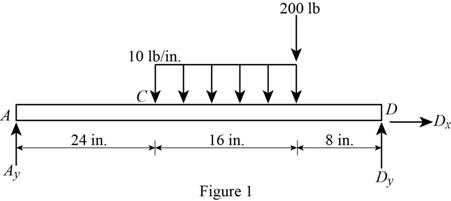
Show the free-body diagram of the beam AD as in Figure 1.

Mechanics of Materials, 7th Edition, Chapter 9.3, Problem 60P

Write the singularity equation for load intensity as follows;

dVdx=w(x)=10x240+10x400

Integrate the equation to find the shear force.

V=Ay10x241+10x401

By definition, the change in bending moment with respect to change in distance is shear force.

dMdx=V=Ay10x241+10x401200x400

Integrate the equation to find the bending moment.

M=Ayx5x242+5x402200x401 (1)

Write the second order differential equation as follows;

d2ydx2=M(x)EI

Here, the moment at the corresponding section is M(x), the modulus of elasticity of the material is E, and the moment of inertia of the section is I.

Substitute (Ayx5x242+5x402200x401) for M(x).

d2ydx2=Ayx5x242+5x402200x401EIEId2ydx2=Ayx5x242+5x402200x401

Integrate the equation with respect to x;

EIdydx=Ayx2253x243+53x403100x402+C1 (2)

Integrate the Equation (2) with respect to x.

EIy=Ayx36512x244+512x4041003x403+C1x+C2 (3)

Boundary condition 1:

At the point D; x=48in.;M=0.

Substitute 48 in. for x and 0 for M in Equation (1).

0=Ay(48)548242+548402200484010=48Ay2,880+3201,600Ay=86.667lb

Boundary condition 2:

At the point A; x=0;y=0.

Substitute 86.667 lb for Ay, 0 for x and 0 for y in Equation (3).

EI(0)=86.667(0)365120244+512040410030403+C1(0)+C20=00+00+0+C2C2=0

Boundary condition 3:

At the point D; x=48in.;y=0.

Substitute 86.667 lb for Ay, 48 in. for x, 0 for y, and 0 for C2 in Equation (3).

EI(0)=86.667(48)3651248244+51248404100348403+C1(48)+00=1,597,446.144138,240+1,706.6666717,066.66667+48C1C1=30,080.128lb-in.2

Determine the moment of inertia (I) of the circular cross section using the equation.

I=πd464

Here, the diameter of the circular cross section is d.

Substitute 1.25 in. for d.

I=π×1.25464=0.119842in.4

At point A; x=0;dydx=θA.

Substitute 29×106psi for E, 0.119842in.4 for I, θA for dydx, 86.667 lb for Ay, 0 for x, and 30,080.128lb-in.2 for C1 in Equation (2).

29×106×0.119842×θA=86.667×(0)22530243+530403100040230,080.12829×106×0.119842×θA=00+0030,080.128θA=8.66×10³rad

At point B; x=24in.;dydx=θB.

Substitute 29×106psi for E, 0.119842in.4 for I, θB for dydx, 86.667 lb for Ay, 24 in. for x, and 30,080.128lb-in.2 for C1 in Equation (2).

29×106×0.119842×θB={86.667×(24)225324243+53244031002440230,080.128}29×106×0.119842×θB=24,960.0960+0030,080.128θB=1.473×10³rad

At point C; x=40in.;dydx=θC.

Substitute 29×106psi for E, 0.119842in.4 for I, θC for dydx, 86.667 lb for Ay, 40 in. for x, and 30,080.128lb-in.2 for C1 in Equation (2).

29×106×0.119842×θC={86.667×(40)225340243+53404031004040230,080.128}29×106×0.119842×θC=69,333.66,826.667+0030,080.128θC=9.33×10³rad

At point D; x=48in.;dydx=θD.

Substitute 29×106psi for E, 0.119842in.4 for I, θD for dydx, 86.667 lb for Ay, 48 in. for x, and 30,080.128lb-in.2 for C1 in Equation (2).

29×106×0.119842×θD={86.667×(48)225348243+53484031004840230,080.128}29×106×0.119842×θD=99,840.38423,040+853.3336,40030,080.128θD=11.847×10³rad

The slope changes from negative to positive in the section BC.

The maximum deflection occurs where the slope changes sign. i.e., dydx=0.

Substitute 0 for dydx, 86.667 lb for Ay, and 30,080.128lb-in.2 for C1 in Equation (2).

EI(0)=86.667xm2253xm243+53xm403100xm40230,080.1280=43.333xm253(xm24)3+0030,080.1280=43.333xm253(xm24)330,080.128

Solve the Equation;

xm=26.4in..

Therefore, the location of the largest downward deflection is xm=26.4in._.

At largest deflection point; xm=26.4in.;y=ym.

Substitute 29×106psi for E, 0.119842in.4 for I, yB for y, 86.667 lb for Ay, 26.4 in. for x, 30,080.128lb-in.2 for C1, and 0 for C2 in Equation (3).

29×106×0.119842×ym={86.667×26.43651226.4244+51226.4404100326.440330,080.128(26.4)+0}=265,775.102213.824+00794,115.3792ym=0.1520in.=0.1520in.()

Therefore, the largest downward deflection of the beam is ym=0.1520in.()_.

Want to see more full solutions like this?

Subscribe now to access step-by-step solutions to millions of textbook problems written by subject matter experts!
Students have asked these similar questions
Knowing that beam AB is an S200 * 34 rolled shape and that P=60 kN, L= 2 m, and E= 200 GPa, determine (a) the slope at A, (b) the deflection at C.
consider the cantilevered W14 x 30 beam shown E = 29(103) ksi, I = 291 in4 determine the maximum slope of the beam, measured counterclockwise from the positive x axis. determine the maximum deflection of the beam. determine the expression for the elastic curve using the coordinate x for 0 < x < 9 ft, where x is in feet.
Determine the slope and deflection at D for the beam and loading shown in Fig, knowing that the flexural rigidity of the beam isEI= 100 MN-m2.

Chapter 9 Solutions

Mechanics of Materials, 7th Edition

Ch. 9.2 - For the beam and loading shown, (a) express the...Ch. 9.2 - (a) Determine the location and magnitude of the...Ch. 9.2 - For the beam and loading shown, determine the...Ch. 9.2 - Knowing that beam AE is a W360 101 rolled shape...Ch. 9.2 - For the beam and loading shown, knowing that a = 2...Ch. 9.2 - Knowing that beam AE is an S200 27.4 rolled shape...Ch. 9.2 - For the beam and loading shown, determine (a) the...Ch. 9.2 - For the beam and loading shown, determine (a) the...Ch. 9.2 - 9.19 through 9.22 For the beam and loading shown,...Ch. 9.2 - 9.19 through 9.22 For the beam and loading shown,...Ch. 9.2 - 9.19 through 9.22 For the beam and loading shown,...Ch. 9.2 - 9.19 through 9.22 For the beam and loading shown,...Ch. 9.2 - For the beam shown, determine the reaction at the...Ch. 9.2 - For the beam shown, determine the reaction at the...Ch. 9.2 - 9.25 through 9.28 Determine the reaction at the...Ch. 9.2 - 9.25 through 9.28 Determine the reaction at the...Ch. 9.2 - Prob. 27PCh. 9.2 - 9.25 through 9.28 Determine the reaction at the...Ch. 9.2 - 9.29 and 9.30 Determine the reaction at the roller...Ch. 9.2 - 9.29 and 9.30 Determine the reaction at the roller...Ch. 9.2 - 9.37 and 9.32 Determine the reaction at the roller...Ch. 9.2 - 9.31 and 9.32 Determine the reaction at the roller...Ch. 9.2 - Prob. 33PCh. 9.2 - 9.33 and 9.34 determine the reaction at A and draw...Ch. 9.3 - 9.35 and 9.36 For the beam and loading shown,...Ch. 9.3 - 9.35 and 9.36 For the beam and loading shown,...Ch. 9.3 - 9.37 and 9.38 For the beam and loading shown,...Ch. 9.3 - 9.37 and 9.38 For the beam and loading shown,...Ch. 9.3 - 9.39 and 9.40 For the beam and loading shown,...Ch. 9.3 - 9.39 and 9.40 For the beam and loading shown,...Ch. 9.3 - 9.41 and 9.42 For the beam and loading shown,...Ch. 9.3 - 9.41 and 9.42 For the beam and loading shown (a)...Ch. 9.3 - For the beam and loading shown, determine (a) the...Ch. 9.3 - For the beam and loading shown, determine (a) the...Ch. 9.3 - For the timber beam and loading shown, determine...Ch. 9.3 - For the beam and loading shown, determine (a) the...Ch. 9.3 - For the beam and loading shown, determine (a) the...Ch. 9.3 - For the beam and loading shown, determine (a) the...Ch. 9.3 - 9.49 and 9.50 For the beam and loading shown,...Ch. 9.3 - 9.49 and 9.50 For the beam and loading shown,...Ch. 9.3 - 9.51 and 9.52 For the beam and loading shown,...Ch. 9.3 - 9.49 and 9.50 For the beam and loading shown,...Ch. 9.3 - For the beam and loading shown, determine (a) the...Ch. 9.3 - For the beam shown, and knowing that P = 40 kN,...Ch. 9.3 - 9.55 and 9.56 For the beam and loading shown, (a)...Ch. 9.3 - 9.55 and 9.56 For the beam and loading shown, (a)...Ch. 9.3 - For the beam and loading shown, determine (a) the...Ch. 9.3 - For the beam and loading shown, determine (a) the...Ch. 9.3 - Prob. 59PCh. 9.3 - 9.59 through 9.62 For the beam and loading...Ch. 9.3 - Prob. 61PCh. 9.3 - 9.59 through 9.62 For the beam and loading...Ch. 9.3 - The rigid bars BF and DH are welded to the...Ch. 9.3 - The rigid bar DEF is welded at point D to the...Ch. 9.4 - Use the method of superposition to solve the...Ch. 9.4 - Use the method of superposition to solve the...Ch. 9.4 - Use the method of superposition to solve the...Ch. 9.4 - Use the method of superposition to solve the...Ch. 9.4 - Use the method of superposition to solve the...Ch. 9.4 - Use the method of superposition to solve the...Ch. 9.4 - Use the method of superposition to solve the...Ch. 9.4 - Use the method of superposition to solve the...Ch. 9.4 - Use the method of superposition to solve the...Ch. 9.4 - Use the method of superposition to solve the...Ch. 9.4 - Use the method of superposition to solve the...Ch. 9.4 - Use the method of superposition to solve the...Ch. 9.4 - Use the method of superposition to solve the...Ch. 9.4 - Use the method of superposition to solve the...Ch. 9.4 - Use the method of superposition to solve the...Ch. 9.4 - Use the method of superposition to solve the...Ch. 9.4 - Use the method of superposition to solve the...Ch. 9.4 - Use the method of superposition to solve the...Ch. 9.4 - Use the method of superposition to solve the...Ch. 9.4 - Prob. 84PCh. 9.4 - Use the method of superposition to solve the...Ch. 9.4 - Use the method of superposition to solve the...Ch. 9.4 - Use the method of superposition to solve the...Ch. 9.4 - Use the method of superposition to solve the...Ch. 9.4 - Use the method of superposition to solve the...Ch. 9.4 - Use the method of superposition to solve the...Ch. 9.4 - Use the method of superposition to solve the...Ch. 9.4 - Use the method of superposition to solve the...Ch. 9.4 - Use the method of superposition to solve the...Ch. 9.4 - Use the method of superposition to solve the...Ch. 9.5 - 9.95 through 9.98 For the uniform cantilever beam...Ch. 9.5 - Prob. 96PCh. 9.5 - 9.95 through 9.98 For the uniform cantilever beam...Ch. 9.5 - 9.95 through 9.98 For the uniform cantilever beam...Ch. 9.5 - 9.99 and 9.100 For the uniform cantilever beam and...Ch. 9.5 - 9.99 and 9.100 For the uniform cantilever beam and...Ch. 9.5 - For the cantilever beam and loading shown,...Ch. 9.5 - Prob. 102PCh. 9.5 - Prob. 103PCh. 9.5 - Prob. 104PCh. 9.5 - Prob. 105PCh. 9.5 - For the cantilever beam and loading shown,...Ch. 9.5 - Two cover plates are welded to the rolled-steel...Ch. 9.5 - Two cover plates are welded to the rolled-steel...Ch. 9.5 - 9.109 through 9.114 For the prismatic beam and...Ch. 9.5 - Prob. 110PCh. 9.5 - Prob. 111PCh. 9.5 - Prob. 112PCh. 9.5 - Prob. 113PCh. 9.5 - Prob. 114PCh. 9.5 - Prob. 115PCh. 9.5 - 9.115 and 9.116 For the beam and loading shown,...Ch. 9.5 - Prob. 117PCh. 9.5 - 9.118 and 9.119 For the beam and loading shown,...Ch. 9.5 - Prob. 119PCh. 9.5 - Prob. 120PCh. 9.5 - Prob. 121PCh. 9.5 - Prob. 122PCh. 9.5 - Prob. 123PCh. 9.5 - Prob. 124PCh. 9.6 - 9.125 through 9.128 For the prismatic beam and...Ch. 9.6 - Prob. 126PCh. 9.6 - Prob. 127PCh. 9.6 - Prob. 128PCh. 9.6 - 9.129 and 9.130 For the beam and loading shown,...Ch. 9.6 - Prob. 130PCh. 9.6 - For the timber beam and loading shown, determine...Ch. 9.6 - Prob. 132PCh. 9.6 - For the beam and loading shown, determine (a) the...Ch. 9.6 - Prob. 134PCh. 9.6 - Prob. 135PCh. 9.6 - Knowing that the beam AD is made of a solid steel...Ch. 9.6 - Prob. 137PCh. 9.6 - For the beam and loading shown, determine (a) the...Ch. 9.6 - Prob. 139PCh. 9.6 - For the beam and loading shown, determine the...Ch. 9.6 - Prob. 141PCh. 9.6 - Prob. 142PCh. 9.6 - Prob. 143PCh. 9.6 - Prob. 144PCh. 9.6 - Prob. 145PCh. 9.6 - For the beam and loading shown, determine (a) the...Ch. 9.6 - Prob. 147PCh. 9.6 - Prob. 148PCh. 9.6 - Prob. 149PCh. 9.6 - Prob. 150PCh. 9.6 - 9.151 and 9.152 For the beam and loading shown,...Ch. 9.6 - Prob. 152PCh. 9.6 - Prob. 153PCh. 9.6 - Prob. 154PCh. 9.6 - Prob. 155PCh. 9.6 - Fig. P9.155 and P9.156 9.156 For the beam and...Ch. 9 - For the loading shown, determine (a) the equation...Ch. 9 - Prob. 158RPCh. 9 - For the beam and loading shown, determine (a) the...Ch. 9 - Determine the reaction at A and draw the bending...Ch. 9 - For the beam and loading shown, determine (a) the...Ch. 9 - For the beam and loading shown, determine (a) the...Ch. 9 - Beam CE rests on beam AB as shown. Knowing that a...Ch. 9 - The cantilever beam BC is attached to the steel...Ch. 9 - For the cantilever beam and loading shown,...Ch. 9 - Knowing that P = 4 kips, determine (a) the slope...Ch. 9 - For the beam and loading shown, determine (a) the...Ch. 9 - Determine the reaction at the roller support and...
Knowledge Booster
Background pattern image
Mechanical Engineering
Learn more about
Need a deep-dive on the concept behind this application? Look no further. Learn more about this topic, mechanical-engineering and related others by exploring similar questions and additional content below.
Similar questions
SEE MORE QUESTIONS
Recommended textbooks for you
Text book image
Elements Of Electromagnetics
Mechanical Engineering
ISBN:9780190698614
Author:Sadiku, Matthew N. O.
Publisher:Oxford University Press
Text book image
Mechanics of Materials (10th Edition)
Mechanical Engineering
ISBN:9780134319650
Author:Russell C. Hibbeler
Publisher:PEARSON
Text book image
Thermodynamics: An Engineering Approach
Mechanical Engineering
ISBN:9781259822674
Author:Yunus A. Cengel Dr., Michael A. Boles
Publisher:McGraw-Hill Education
Text book image
Control Systems Engineering
Mechanical Engineering
ISBN:9781118170519
Author:Norman S. Nise
Publisher:WILEY
Text book image
Mechanics of Materials (MindTap Course List)
Mechanical Engineering
ISBN:9781337093347
Author:Barry J. Goodno, James M. Gere
Publisher:Cengage Learning
Text book image
Engineering Mechanics: Statics
Mechanical Engineering
ISBN:9781118807330
Author:James L. Meriam, L. G. Kraige, J. N. Bolton
Publisher:WILEY
Solids: Lesson 53 - Slope and Deflection of Beams Intro; Author: Jeff Hanson;https://www.youtube.com/watch?v=I7lTq68JRmY;License: Standard YouTube License, CC-BY