
Concept explainers
Videos
9.98 though 9.102 Using Mohr’s circle, determine for the area indicated the orientation of the principal centroidal axes and the corresponding values of the moments of inertia.
9.99 Area of Prob. 9.76
9.75 through 9.78 Using the parallel-axis theorem, determine the product of inertia of the area shown with respect to the centroidal x and y axes.
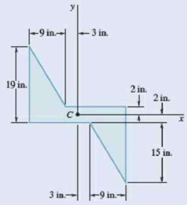
Fig. P9.76
Find the orientation of the principal axes at the origin and the maximum minimum value of moment of inertia.
Answer to Problem 9.99P
The orientation of the principal axes at the origin is
The maximum moment of inertia is
The minimum moment of inertia is
Explanation of Solution
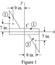
Sketch the cross section as shown in Figure 1.
Express the product of inertia as shown below:
Here,
Applying parallel axis theorem for each triangle,
When the x and y axis is symmetry.
Refer to sample problem 9.6 in the textbook.
The sign of
Refer to Figure 1.
Find the area of rectangular section 2 as shown below:
Here,
Substitute
Find the area of rectangle section 3 as shown below:
Here,
Substitute
Find the centroid
Find the centroid
Find the centroid
Find the centroid
Find the product of inertia of the area with respect to x and y axes by using parallel axis theorem as shown below:
Substitute
Find the product of inertia as follows:
Substitute
Find the moment of inertia for section 1 about x axis as shown below:
Here, b is the width of the section 1 about x axis and h is the height of the section 1about x axis.
Substitute
Find the moment of inertia for section 2 and 3 about x axis as shown below:
Here, b is the width of the section 2 and h is the height of the section 2.
Substitute
Find the total moment of inertia
Substitute
Find the moment of inertia for section 1 about y axis as shown below:
Here, b is the width of the section 1 about y axis and h is the height of the section 1 about y axis.
Substitute
Find the moment of inertia for section 2 and 3 about y axis as shown below:
Substitute
Find the total moment of inertia
Substitute
Consider the point X with co-ordinates
The diameter of the Mohr circle is defined by XY distance. It is expressed as follows:
Consider that the average moment of inertia
Find the average moment of inertia
Here,
Substitute
Find the radius (R) using the relation as shown below:
Here, R is radius and
Substitute
Draw the Mohr circle using the procedure as follows:
- Plot the point X with coordinate
- Joint the points X and Y with straight line, which is defined as center of the circle (C).
- Plot the circle using the center point and diameter (XY).
Sketch the Mohr circle as shown in Figure 2.
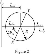
Refer to Figure 2.
Substitute
Thus, the orientation of the principal axes at the origin is
Sketch the orientation of the principal axes as shown in Figure 3.
Sketch the cross section as shown in Figure 3.
Find the maximum moment
Substitute
Thus, the maximum moment of inertia is
Find the minimum moment
Substitute
Thus, the minimum moment of inertia is
From the Mohr’s circle, the axis a represents
Want to see more full solutions like this?
Chapter 9 Solutions
Vector Mechanics for Engineers: Statics


- Determine by direct integration the moment of inertia of the shaded area with respect to the x axis.Fig. P9.11arrow_forwardIt is known that for a given area Iy = 48 x 106 mm4 and Ixy = -20 x 106 mm4, where the x and y axes are rectangular centroidal axes. If the axis corresponding to the maximum product of inertia is obtained by rotating the x axis 67.5° counterclockwise about C , use Mohr’s circle to determine (a) the moment of inertia Ix of the area, (b) the principal centroidal moments of inertia.arrow_forwardDetermine the moment of inertia (in4) Īx of the area shown with respect to the horizontal line that passes to the centroid of the composite area if b = 6.31 in, h = 0.76 in, L = 8.49 in, and W = 0.76 in. Round off only on the final answer expressed in 3 decimal places.arrow_forward
- For the area indicated, determine the orientation of the principal axes at the origin and the corresponding values of the moments of inertia.Area of Prob. 9.73(Reference to Problem 9.73):Using the parallel-axis theorem, determine the product of inertia of the area shown with respect to the centroidal x and y axes.arrow_forwardDetermine the moment of inertia (in4) Ix of the area shown with respect to the horizontal line that passes to the centroid of the composite area if b= 6.11 in, h= 0.72 in, L= 8.39 in, and W = 0.77 in. Round off only on the final answer expressed in 3 decimal places.arrow_forwardA channel and a plate are welded together as shown to form a section that is symmetrical with respect to the y axis. Determine the moments of inertia of the combined section with respect to its centroidal x and y axes.arrow_forward
- determine the centroidal polar moment of inertia of a rectangle 100mm wide by 200 mm higharrow_forwardFor the figure shown knowing that a = 1.00 cm and b = 4.00 cm, determine:(a) The centroid of the figure shown.b) The moments of inertia Ix and Iy and the product of inertia Ixy about the x and y axes.c) The angle m corresponding to the location of the principal axes.d) For the u-v axes shown and obtained by rotating an angle = 34.0° clockwise, the corresponding momentsand product of inertia using Mohr's circle.arrow_forwardDetermine the shaded area and its moment of inertia with respect to the centroidal axis parallel to AA, knowing that d1 = 25 mm and d2 = 10 mm and that its moments of inertia with respect to AA' and BB' are 2.2 × 106 mm4 and 4x 106 mm4, respectively.arrow_forward
- Two 20-mm steel plates are welded to a rolled S section as shown.Determine the moments of inertia and the radii of gyration of the combined section with respect to the centroidal x and y axes.arrow_forwardTwo L4 × 4 × 1/2-in. angles are welded to a steel plate as shown.Determine the moments of inertia of the combined section with respect to the centroidal axes that are respectively parallel and perpendicular to the plate.arrow_forward
 Elements Of ElectromagneticsMechanical EngineeringISBN:9780190698614Author:Sadiku, Matthew N. O.Publisher:Oxford University Press
 Mechanics of Materials (10th Edition)Mechanical EngineeringISBN:9780134319650Author:Russell C. HibbelerPublisher:PEARSON
 Thermodynamics: An Engineering ApproachMechanical EngineeringISBN:9781259822674Author:Yunus A. Cengel Dr., Michael A. BolesPublisher:McGraw-Hill Education
 Control Systems EngineeringMechanical EngineeringISBN:9781118170519Author:Norman S. NisePublisher:WILEY
 Mechanics of Materials (MindTap Course List)Mechanical EngineeringISBN:9781337093347Author:Barry J. Goodno, James M. GerePublisher:Cengage Learning
 Engineering Mechanics: StaticsMechanical EngineeringISBN:9781118807330Author:James L. Meriam, L. G. Kraige, J. N. BoltonPublisher:WILEY