What is an Electrical Circuit?
Electric circuits are a network that comprises of a closed-loop, which helps in providing a return path for the current through a switch. When the switch is activated, the load operates, and the current accepts a path to finish the circuit at a low potential level from the opposing high potential level. Electric circuits theory is a linear analysis that helps in establishing a linear relation of voltage and current for R (resistance), L (inductance), and C (capacitance).
How Does it Work?
Imagine a tank above ground used to store water with an outlet pipe at its bottom. The amount of water in the tank is analogous to charge (similar to a battery), the water pressure at the end of the pipe can represent voltage, and the flow rate at the pipe outlet is equivalent to current. When water (charge) begins to drain, the pressure (voltage) at the pipe outlet will decrease causing the flow (current) to reduce. Resistance can be related to the width of the outlet pipe, which means that a bigger pipe will have lesser resistance as compared to a smaller pipe with the pressure (voltage) being constant. Thus, the flow rate (current) is also dependent on the width of the pipe (resistance).
Circuit Design
A basic point that one needs to understand is that circuit theory is based on the design, application, and connectivity of electrical components utilized to make a circuit.
There are several terms that are utilized in circuit theory like circuit, linear circuit, non-linear circuit, passive network, active network, parameters, branch, loop, node, etc. An electric circuit comprises of electric elements, and the elements of circuit theory establish 2 kinds of networks, namely parallel network and series network. Such networks can be understood with the help of examples such as series resistance, parallel resistance, series and parallel capacitance, & series and parallel induction.
Electric circuits are the collections of tools and materials required to combine the source of power to the user or design which utilizes it. Intelligence systems, network systems, and control systems all include either limited or complex electrical circuits which themselves are built up of individual circuit components. The tools and accessories mentioned may be described by ‘equivalent circuits’ containing these circuit components, and a similar circuit must work to all plans and designs in an identical method as the equipment or devices which it serves. In other words, if the design were put into an individual ‘black box’ and the similar circuit was put into a different ‘black box’, an external spectator of the performance would be unable to differentiate between the genuine device and the comparable circuit.
Here is a simple design of a circuit which includes a source (battery), wire and a bulb.
Series and Parallel Resistance
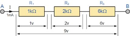
When resistors R1, R2….Rn (where n is the total number of resistors) are joined end-on-end as shown, they are said to be connected in series. It can be proved that the equivalent resistance or total resistance between them is equal to the sum of the individual resistances.
In a series circuit the current is the same through all the conductors, but the voltage drop across each one is different due to different resistance of each. The total resistance R is equal to
Example 1
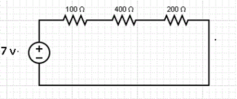
In this circuit, the value of current & voltage is calculated for each resistor. For calculating current, we need to calculate total resistance first.
Total resistance = 100 ohm + 400 ohm + 200 ohms = 700 ohm
Now, the current is calculated with the help of Ohm’s law V = IR
Hence, I = V/R=> I = 7/700 = 0.01Amp
The voltage across each resistor can also be calculated as
Voltage at 100-ohm
Voltage at 400-ohm
Voltage at 200-ohm
In this way, the series resistance, current and voltage is calculated with the help of Ohm’s law
When resistors R1, R2 …. Rn is connected in parallel as shown in the figure, the voltage drop is similar across all the resistors, but the current in each resistor is distinctive, and it is given by Ohms law. The cumulative current is the addition of the individual currents, so the comparable resistance R of all the resistors in correspondence is equal to the complementary of the entire (total) resistance of the reciprocals of their individual resistances.
Series and Parallel Capacitance
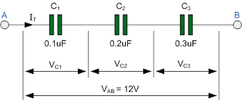
When capacitors C1, C2 …..Cn are joined in series as shown in the figure, then the equivalent capacitance C of all capacitors joined in series is equivalent to the reciprocal of the addition of the reciprocals of their individual capacitance.
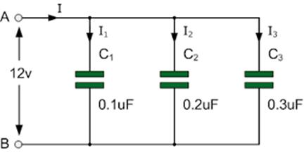
When any capacitors C1, C2 …..Cn are connected in parallel as presented in the figure, the equivalent capacitance C of all the capacitors joined in parallel is equivalent to the addition of their individual capacitances.
Series and Parallel Inductance
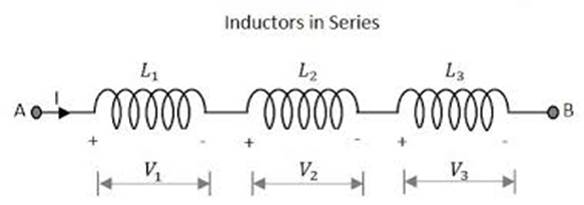
Similarly when any number of inductors, of L1, L2…..Ln are joined in series as presented, the equivalent inductance L is equal to the sum of their separate inductance joined in the circuit.
When inductors L1, L2…..Ln are joined in parallel, the equivalent inductance L of inductors in parallel is equivalent to the reciprocal of the addition of the reciprocals of their individual inductance.
Application of Circuit Theory
Circuit theory follows a few laws of Electricity that are Ohm’s law, Kirchhoff’s current and voltage law, Norton’s theorem, Superposition theorem, Thevenin theorem among others.
Ohm’s Law
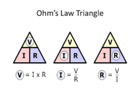
The electrical theorems are pertained to the electrical network to clarify and to find the emulsion of the electrical network. The voltage beyond resistance is equivalent to the product of the resistance and the current flowing through it.
Voltage = Resistance × Current.
Kirchhoff’s Current and Voltage Law
Kirchhoff’s current law says that in any current passing closed loop, the algebraic sum of currents reaching at a junction is zero. Thus total current entering and leaving the junction is same.
Incoming current = Outgoing current
Kirchhoff’s law says that the algebraic addition of the product of currents and resistance in each of the elements in any closed loop in a network and the EMF of the voltage sources present in that loop is zero.
EMF Voltage in the circuit = 0
Norton’s theorem
Norton's Theorem states that it is probable to interpret any linear circuit, no concern how complicated, to an equivalent circuit with just a separate current source and parallel resistance joined to a load.
Norton resistance
Superposition theorem
The superposition theorem affirms that a circuit with versatile voltage and current references is equivalent to the addition of uncomplicated circuits using just one of the sources.
In this way, all the laws of electric circuits can be illustrated in brief. It is not easy to complete the explanation of circuit theory in brief because the fundamentals of circuit theory are not a small topic. It covers many points with sub-points.
Formula
| Resistance |
|
| Capacitance |
|
| Inductance | |
| Ohm’s law | |
| Kirchhoff’s current and voltage | |
| Norton’s Theorem |
Fundamental Use
There are different applications of circuit theory with different types of circuits. The fundamental use of circuit is to calculate current, voltage, resistance, capacitance, inductance, among others.
Common Mistake
The common mistake made by students in performing circuit analysis theory is getting confused with the content and formulas of different theorems and problem. The steps used in the theorems get displaced, and the students make mistake in this place of calculation.
After calculation of circuit with proper measurement of current and voltage, it is essential that students recalculate the values from the circuit.
Context and Applications
This topic is significant in the professional exams for both undergraduate and graduate courses
- Bachelors in Technology Electrical and Electronics Engineering
- Bachelors in Technology Electrical Engineering
- Bachelors in Technology Electronics and Instrumentation Engineering
- Bachelors in Technology Instrumentation and Control Engineering
- Bachelors in Science (Physics)
Want more help with your electrical engineering homework?
*Response times may vary by subject and question complexity. Median response time is 34 minutes for paid subscribers and may be longer for promotional offers.
Search. Solve. Succeed!
Study smarter access to millions of step-by step textbook solutions, our Q&A library, and AI powered Math Solver. Plus, you get 30 questions to ask an expert each month.
Circuit Theory Homework Questions from Fellow Students
Browse our recently answered Circuit Theory homework questions.
Search. Solve. Succeed!
Study smarter access to millions of step-by step textbook solutions, our Q&A library, and AI powered Math Solver. Plus, you get 30 questions to ask an expert each month.