11:22 Chapter 7 Homework Done ( Chapter Seven Book Problems Problems 1. In Figure 7-20, use the superposition theorem and determine the voltage across R₁ and R2. www 10 ԱՈ V20 V 20V系 R₂ 10 kn w FIGURE 7-20 ww 15 KO 18 k 27kf w FIGURE 7-21 3. In Figure 7-21, use Thevenin's theorem and determine VTH, RTH, IL, and VL. Assume R₁ is 10 ΚΩ. 4. Refer again to Figure 7-21. Assume R₁ changes to 27 kQ. What are the values of VTH, RTH, IL, and V₁? 5. Draw and label the values for the Norton equivalent circuit for the circuit in question 3. 8. If the voltage at the source terminals of a circuit is 100 V without load and 90 V when 10 A are drawn from the source, what value is the load resistance to afford maximum power transfer? FB 100 V source FIGURE 7-24 5.60 10 10. For the circuit in Figure 7-24, what are the values of RN and IN? 11. Convert Norton parameters to Thevenin parameters, given IN-3 A and RN-100. 12. Convert Thevenin parameters to Norton parameters, given RTH-15 Qand VTH=25 V. 13. What is the percentage of efficiency for a circuit whose 100-V source has an internal resistance of 5 and a load resistance of 25 ? 14. Would the percentage efficiency be the same for the circuit described in question 13 if the source voltage were 200 V? Does the value of source voltage have any impact on the circuit's efficiency factor? (Meade & Diffenderfer, 2007)
11:22 Chapter 7 Homework Done ( Chapter Seven Book Problems Problems 1. In Figure 7-20, use the superposition theorem and determine the voltage across R₁ and R2. www 10 ԱՈ V20 V 20V系 R₂ 10 kn w FIGURE 7-20 ww 15 KO 18 k 27kf w FIGURE 7-21 3. In Figure 7-21, use Thevenin's theorem and determine VTH, RTH, IL, and VL. Assume R₁ is 10 ΚΩ. 4. Refer again to Figure 7-21. Assume R₁ changes to 27 kQ. What are the values of VTH, RTH, IL, and V₁? 5. Draw and label the values for the Norton equivalent circuit for the circuit in question 3. 8. If the voltage at the source terminals of a circuit is 100 V without load and 90 V when 10 A are drawn from the source, what value is the load resistance to afford maximum power transfer? FB 100 V source FIGURE 7-24 5.60 10 10. For the circuit in Figure 7-24, what are the values of RN and IN? 11. Convert Norton parameters to Thevenin parameters, given IN-3 A and RN-100. 12. Convert Thevenin parameters to Norton parameters, given RTH-15 Qand VTH=25 V. 13. What is the percentage of efficiency for a circuit whose 100-V source has an internal resistance of 5 and a load resistance of 25 ? 14. Would the percentage efficiency be the same for the circuit described in question 13 if the source voltage were 200 V? Does the value of source voltage have any impact on the circuit's efficiency factor? (Meade & Diffenderfer, 2007)

Delmar's Standard Textbook Of Electricity
7th Edition
ISBN:9781337900348
Author:Stephen L. Herman
Publisher:Stephen L. Herman
Chapter8: Combination Circuits
Section: Chapter Questions
Problem 5RQ: Refer to Figure 8-21. Assume that the resistors have the following values: R1=150R2=120R3=47R4=220...

Related questions
Question
Help.
Transcribed Image Text:11:22
Chapter 7 Homework
Done
(
Chapter Seven Book Problems
Problems
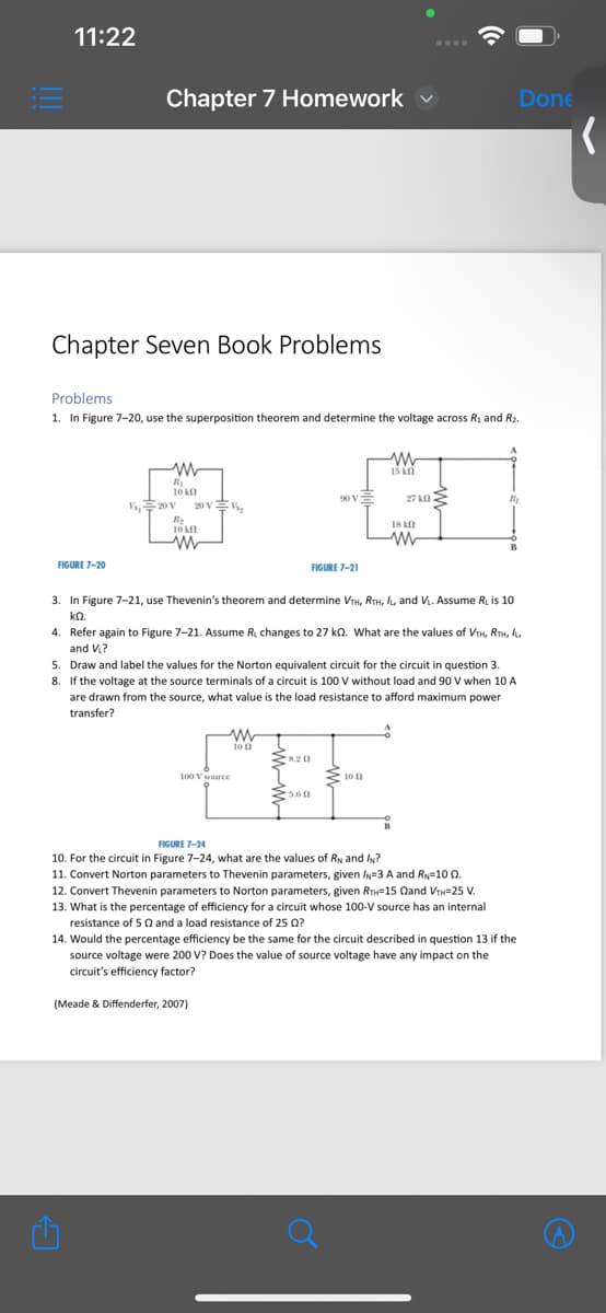
1. In Figure 7-20, use the superposition theorem and determine the voltage across R₁ and R2.
www
10 ԱՈ
V20 V
20V系
R₂
10 kn
w
FIGURE 7-20
ww
15 KO
18 k
27kf
w
FIGURE 7-21
3. In Figure 7-21, use Thevenin's theorem and determine VTH, RTH, IL, and VL. Assume R₁ is 10
ΚΩ.
4. Refer again to Figure 7-21. Assume R₁ changes to 27 kQ. What are the values of VTH, RTH, IL,
and V₁?
5. Draw and label the values for the Norton equivalent circuit for the circuit in question 3.
8. If the voltage at the source terminals of a circuit is 100 V without load and 90 V when 10 A
are drawn from the source, what value is the load resistance to afford maximum power
transfer?
FB
100 V source
FIGURE 7-24
5.60
10
10. For the circuit in Figure 7-24, what are the values of RN and IN?
11. Convert Norton parameters to Thevenin parameters, given IN-3 A and RN-100.
12. Convert Thevenin parameters to Norton parameters, given RTH-15 Qand VTH=25 V.
13. What is the percentage of efficiency for a circuit whose 100-V source has an internal
resistance of 5 and a load resistance of 25 ?
14. Would the percentage efficiency be the same for the circuit described in question 13 if the
source voltage were 200 V? Does the value of source voltage have any impact on the
circuit's efficiency factor?
(Meade & Diffenderfer, 2007)
Expert Solution
This question has been solved!
Explore an expertly crafted, step-by-step solution for a thorough understanding of key concepts.

This is a popular solution!

Trending now
This is a popular solution!

Step by step
Solved in 2 steps with 11 images

Recommended textbooks for you
Delmar's Standard Textbook Of Electricity
Electrical Engineering
ISBN:
9781337900348
Author:
Stephen L. Herman
Publisher:
Cengage Learning
Delmar's Standard Textbook Of Electricity
Electrical Engineering
ISBN:
9781337900348
Author:
Stephen L. Herman
Publisher:
Cengage Learning