2) Given the following excitation and output equations, write the state transition and output tables. X is the input, Z is the output. Draw the sequential logic circuit. Please note that state memory is using positive-edge triggered D flip-flops. D1Q1'+ Q1 Q2 D2 = Q2'-X' Z = Q1' + Q2
Q: Three loads, each with resistance 40Ω , are star connected to a 363.73V , 3-phase supply. a)…
A: The objective of the question is to determine the phase voltage, phase current, and line current of…
Q: A band-limited signal with a maximum frequency of 5 kHz is to be sampled. According to the sampling…
A: The given data is shown below:Bandlimited signal with a maximum frequency of up to 5kHz is to be…
Q: A circuit is given according to the diagram below a) Calculate R1 b) Calculate I2 c) Calculate R2 d)…
A: Solved below .Explanation:
Q: In the circuit of Fig. 7.79, the capacitor voltage just before t Ois: (a) 10 V (b) 7 V (c) 6 V (d) 4…
A: The given data is shown below:
Q: Implement circuit. A using 3 Bid смоя
A:
Q: Please step by step full answer
A: Please refer below pages.Explanation:Step 1: Step 2: Step 3:
Q: Circuit Theory: I have this following circuit but its not producing the correct output. My input is…
A: Please refer below pages.If you have any doubts please feel free to ask.Explanation:Step 1: Step 2:…
Q: B. Define the following terms with aid of diagrams 1- nondirectional overcurrent relay 2- Biased…
A: "Since you have posted a question with multiple sub parts, we will provide the solution only to the…
Q: 1.) Define transducer 2.) What are the different types of transducer 3.) What are actuators and how…
A: Please see the explanation for the answer.Explanation:Answer 1. A transducer is basically a device…
Q: Q/ Find Vo and I? Hint: one Nodeequation only needed. 3V +- ΑΚΩ ΩΚΩ ми ww + I 6v 2mA
A: The circuit diagram,
Q: Determine the network function, H(w): Vo(w) = of the circuit shown in Figure 1. Vi(w)' 302 0.2F √(x)…
A: In this question, we need to determine the transfer function. H(w) =
Q: Needs Complete solution with 100 % accuracy.
A: The objective of the question is to calculate the input power to a DC series motor powered by a…
Q: Find vol for all t> 0 in the given circuit. Assume /= 2u(t) A. 102 ww 7u(t) V ΙΩ ww + 1 H 0.5 F νο…
A: In the given questions we need to calculate the output voltage.
Q: Two resistors and a capacitor are connected in a network with a switch S. The switch S has been open…
A: See the attachments given below for detailed explanation please let me know if you find any…
Q: Needs Complete solution with 100 % accuracy.
A: The objective of the question is to find the increase in the charge and the potential difference…
Q: The circuit in the figure is fed by a sinusoidal alternating voltage with a frequency of 50 Hz. The…
A: a) 11.31 Ab) 0.782 ohmc) 120.325 Vd) 85.785 degExplanation:Given C= 300 μQ. I am assuming the…
Q: 1. a) Use node-voltage method to find v₁, v₂ and v3 in the circuit shown in below. b) How much power…
A: The given data is shown below:
Q: me In the diagram below, the EMF provides a potential € = 9.0 V. All of the capacitors have a…
A: Given:with we need to find:a) equivalent capacitance of the circuit.b) Charge on capacitor C2.
Q: Use the mesh-current method to find the branch currents 1-16 in the circuit shown in (Figure 1).…
A:
Q: 1. a) Use node-voltage method to find v₁, v₂ and v3 in the circuit shown in below. b) How much power…
A: Kirchhoff's Current Law (KCL) is a fundamental principle in electrical engineering that states that…
Q: Converters 1) Consider the circuit below and solve for the following (all opamps are ideal and have…
A: In this question, we need to determine the output voltage Vout and current iout . We solve this…
Q: For the energy conversion system shown in Fig., if the airgap length is reduced from x = 0.05 to…
A: In the given question we need to discuss about the effect of reducing the air gap length.
Q: S+10 s(s+5)2* 1. Obtain Bode plot for the system represented by system and estimate phase margin and…
A: Given:Loop transfer function, we need to obtain bode plot and comment on stabilty using phase margin…
Q: Figure £7.9 E7,10 Find i(r) for t > 0 in Fig. E7.10 using the step-by-step method. 1-0 oto 12 V…
A: To determine io(t) for t>0 og given figure
Q: Figure E26.26 2.00 10.00 V ww a 3.00 Ω 1.00 5.00 V 4.00 Ω b wwww 10.00 Ω www 26.27 The 10.00 V…
A: The circuit diagarm,
Q: Three loads are connected in parallel to a 1400 Vrms, 60 Hz single-phase source. Load 1: Inductive…
A: The circuit diagram,
Q: The transistor circuit below is biased with a constant current source / = 1 mA. Assume an R₁=10 KQ…
A: We are given,I=1mARL=10KΩa) Redraw the circuit as an amplifier in CE configuration. Find the core…
Q: Consider the system represented by the differential equation. d³y dt³ d²y + 6- +11+6y dt² dy dt du…
A: A system is described by the differential equation :⇒d3ydt3+6d2ydt2+11dydt+6y=18dudt+6u ;1. We need…
Q: i. Express the voltage and current in the line in terms of the forward and backward travelling…
A: Given parameters a lossless transmission line terminated with a load Z1 has characteristic impedanc…
Q: 33. For the circuit of Figure 2.40, determine the circulating current and the voltages across each…
A: In this question, we need to determine the circulating current and voltage across each element.we…
Q: Two batteries have each been measured with the following data: E1 = 33.6 V, R1 = 2.2 Ω E2 = 24 V, R2…
A: a. Calculate the current flowing through circuit.b. Calculate the voltage UAB c. What is the…
Q: Identify the second-order responses illustrated below.
A: See the attachments given below for detailed explanation.Explanation:Graph no 1 is of underdamped…
Q: determine the initial voltage across each component for the circuit below
A: The initial voltage across the 2Kohm resistor is V2Kohm=3.3333volts,The initial voltage across the…
Q: Consider the circuit shown in the given figure. (Given: A = 4.000.) 10 Ω ww 1 H 2 cos 101 V 5H 3H ΑΩ…
A: Average power, also known as real power or active power, is the power consumed by a circuit that is…
Q: 4 (Mesh analysis) Using med Analysis, determine the mesh currentsber the network www Ru R9.1152 E +…
A: The circuit diagram,
Q: 5.2-8 A signal bandlimited to 1 MHz is sampled at a rate 30% above the Nyquist rate and quantized…
A:
Q: The circuit in the figure below is fed by an alternating voltage with the rms value U. The resistor…
A: The objective of the question is to calculate the reactance X, current I, voltage U, and impedance Z…
Q: 4- a) Show that the circuit of figure on the left indicated with letter "a" can be replaced by that…
A: Source current will never effected by transferring impedance from one side to another side
Q: In the ideal Transformer given below find the power absorbed by the load. Primary and secondary…
A: The given data is shown below:
Q: Design a sequential circuit that implements the following state transition table using JK Flip…
A: Given:State transition table, we need to design a sequential circuit that implements the above table…
Q: Assume an ideal-offset model for the diode with VON = 1 V. = Given Is 2 mA and R = = 1 k, find the…
A: The resistor, The source current, Diode voltage,
Q: Q2-E=(B-15)-(C+4A) +1 when B=FAh, C=10h
A: A microprocessor is a processing unit that is used to process and perform different set of…
Q: 4. A sample of intrinsic GaN is illuminated with a 10 mW/cm² beam of light at the blue edge of what…
A: “Since you have posted a question with multiple sub parts, we will provide the solution only to the…
Q: Problem 1 1A) Find the output voltage with superposition theorem. Add ground to the bottom node…
A: In this question, we need to determine the voltage Vo using the superposition theorem.
Q: A 12 V lead-acid car battery has a measured voltage of 11.2 V when delivers 40 A to a load. What…
A:
Q: 3. In a TEM using beam energy of 70 keV, if the film thickness is t = 30 nm, and magnetic inductance…
A: Given parametersBeam energy =70keVFilm thickness is t=30nmMagnetic inductance due to in-plane…
Q: Find V_a and V_b
A: The circuit diagram,
Q: a. Determine the inductor and capacitor values for a "pi" (n) configured constant-K, band-stop…
A: Details solution is given below Explanation:Step 1:#i am including the matlab code :function…
Q: For a certain alternating current, i(t), [A] i = 2 ⋅ sin (500 π ⋅ t + ) π, where the time is in…
A: The objective of the question is to determine the peak value, rms value, period, and frequency of…
Q: I want name tags…… A question comes up, you circle it and say what is the name of this?
A: This answer is given below.Explanation:
Alert dont submit AI generated answer.
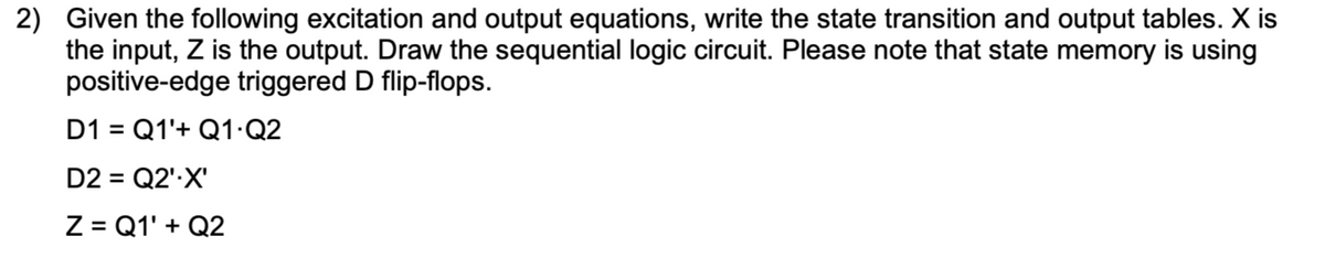
Trending now
This is a popular solution!
Step by step
Solved in 3 steps with 3 images
- Implement a 4-bit synchronous up counter with positive edge triggered D flip flops by doing thefollowing. Up counter means counting from 0000, 0001, 0010, ... to 1111, then 0000, 0001, ....1) Derive a state table for this counter with D flip flop.2) Develop state input equations.3) Sketch a logic diagram for this counteYou are asked to design a synchronous counter that will count the sequence 1 > 2>3>1. (a) Represent these decimal numbers in 2 bits binary numbers. (b) Write down the state table. (c) Find the functions for the next state of the state table using K-map. (d) Draw the circuit (You need to consider D flip-flops as memory unit).Design 2 bits counter that count down by using T flip flop when input x =1 and counts upwhen x=0. Find the following1. Derive the state table2. Derive the K‐map simplifications.3. Draw the logic diagram
- Draw a logic diagram of a 4-bit shift register, using D flip-flops, with mode selection inputsS1, S2 to operate according to the following function table: (Please provide actual diagram of the flip-flop circuit)Q5 A Moore machine is to detect three or more consecutive zeros on an input bitstream using D flip flops. (a) Present the truth table and state diagram. (b) Interpret the simplified logic expression using K-Map. (c) Sketch the circuit with appropriate labeling.2- Using JK Flip flops, a 2-bit counter will be designed that will count down ((11-10-01-00) when the input is "0") and the random sequence given when the input is "1" (00-01-11-10). a) Construct the state table for the sequential circuit. b) Obtain the simplified input equations for flip-flops. c) Draw the logic circuit for the 2-bit counter.
- 1. Design a 16 - to - 1 multiplexer using 4- to-1 multiplexer. 2. Using K- Map, simplify the following Boolean expression : Y = Σ (1,3,5,7,9,10,11,13,14,) 3. Build the logic circuit for the following function using Programmable Logic Array (PLA). ?? = ??? + ??? + ??? + ??? ?? = ??? + ??? + ??? + ???Using D- Flip flops when input is “0” downwards ((11-10-01-00)) when input is “1”A 2-bit counter will be designed to count the given random sequence (00-01-11-10).a) Construct the state table for the sequential circuit.b) Obtain the simplified input equations for flip-flops.c) Draw the logic circuit for the 2-bit counter.B) A coin-operated cold drink dispenser will provide cold drink (D) under the following conditions: The correct coin (C) is inserted AND A paper cup is in position (P) AND The selector is set t Orange (O) OR Sprite (S) OR Lemonade (L) Write the Boolean expression for the output of the dispenser. Represent the operation of the dispenser in logic circuit 4 get a logic circuit to mimic aorporate checquing system for operatore of a compnny
- Design a three bit synchronous binary counter that counts two by two with T-flipflops,continously. Output should be one when the counter equals maximum number.a. Draw the exitation table b. Draw the corresponding state diagram. c. Tabulate the state table for the sequential circuit. d. Draw the logic diagram of the circuit.a) Design a logic circuit with three inputs A, B, C and an output that goes LOW only when A is HIGH while B and C are different. Draw and upload the circuit if you can, or at least describe it in words. b) Which logic gates produce a 1 output in the disabled state? c) Which logic gates pass the inverse of the input signal when these gates are enabled? d) What is the normal resting state of the SET’ and RESET’ inputs of a latch circuit (the prime is same as bar)? What is the active state of each input? e) What is the normal resting state of the NOR latch inputs? What is the active state?Solve the following in Boolean Algebra: (BC'+A'D)(AB'+CD') A. Simplify the given function using Boolean simplification. B. Draw the logic diagram of the given equation. C. Draw the logic diagram of the simplified equation. D. Give the number of of logic gates used in the given design E. Give the number of logic gates used in the simplified design.