
Elements Of Electromagnetics
7th Edition
ISBN: 9780190698614
Author: Sadiku, Matthew N. O.
Publisher: Oxford University Press
expand_more
expand_more
format_list_bulleted
Related questions
Concept explainers
Question
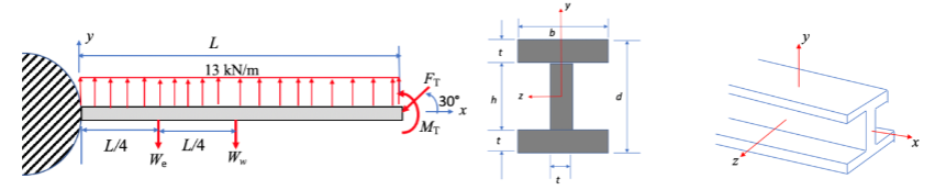
3) The force, FT = 1 kN, and moment, MT = 0.5 kN-m, at the tip are caused by a wing tip vortex
and a winglet, not shown. L = 12 m and the spar has an elastic modulus of E = 70 GPa and a
Poisson’s ratio of n = 0.33. The mass of the wing is 4000 kg, and the weight of the engine is 107
kN. Use 9.8 m/s 2 for the acceleration due to gravity.
Consider the cross-section shown (you can look these up). Pay attention to the coordinate system
given in the drawing.
d) where is the centroid?
e) what is the area?
f) Calculate the shear modulus

Transcribed Image Text:L/4
We
L
13 kN/m
L/4
Ww
FT
30°
MT
t
H
Expert Solution
This question has been solved!
Explore an expertly crafted, step-by-step solution for a thorough understanding of key concepts.

This is a popular solution

Trending nowThis is a popular solution!

Step by stepSolved in 4 steps with 28 images

Knowledge Booster


Learn more about
Need a deep-dive on the concept behind this application? Look no further. Learn more about this topic, mechanical-engineering and related others by exploring similar questions and additional content below.Similar questions
- 10. Bar ABCD rests against a smooth surface at end D and is supported at end A with a ball-and-socket joint. There is a journal bearing at B that is properly aligned and that doesn't exert thrust. The force vector at C is Fc = {−100i + 350j - 280k} N. Select the correct equation for summing moments (in N m) about the y-axis. Unknown support reactions are assumed to be in the positive direction. a) Ax (0.5) - Az (0.5) - (100) (0.25) - (280) (0.4) = 0 b) Bx(0.2) - B₂(0.2) - (350) (0.25) + Dx (0.4) = 0 c) -Ay(0.5) - (100) (0.25) - (350) (0.25) + D (0.5) = 0 d) -B₂(0.25) - (100) (0.4) + (280) (0.25) + Dx (0.4) = 0 e) None of the above. X N A F C D 400 mm 300 mm/200 mm, B 250 mm yarrow_forwardFor the frame structure as in the figure, determine the total moment at : MA ,MB, MOarrow_forward]: A horizontal beam with a length of 4.5 m is subjected to the shown loading. The forces are vertical and the couple moment is applied at point D. The figure is not to scale. 3 kN/ m 1 kN/ m 3 kNm A В C D E 1 т 1.5 m 0.5m 1.5m 0.6 KN 1.35KN (a) Motivate with substantiating explanations and clear and applicable calculations why the beam is in equilibrium. (b) Draw the shear force and bending moment diagrams for the beam. Calculate all local maxima and minima, zeros and points where the diagrams change shape, and show these values and points on the diagrams.arrow_forward
- A 4.8 m-long from fixed point, 0.5 m wide and ssumed a thickness of 30 mm troughout a springboard made of high strengh S-2 glassfiber material which weighs 3.6-kN/m. If a diver impacts 30-kN at the free-end of the board when about to dive, calculate: i. the reaction at the fixed-end of the cantilever and bending moment diagram. ii. the maximum bending moment in the beam. if the material Young's Modulus of elasticity is 93.8 GPa find: iii the maximum slope of the beam. iv. the maximum deflection in the beam. v. the maximum strength in the materialarrow_forwardTwo street lights are mounted as shown in the figure one at A and the other at C. The member AD is able to freely rotate about D. Member BE is a steel cable. B. EACH street light has a mass of 5 kg, AB=20cm, BC=20cm, CD=10cm, DE=17.32cm. Assume gravity is 9.81 N/kg. h=4cm Draw the shear force profile (a) between point A and D. On the diagram, clear indicate the values on the diagram. (b) member just to the right of point B. Calculate the maximum bending shear stress. At what distance from the bottom does it occur? Consider a cross-section of the (c) distance from the bottom does the minimum bending shear stress occur? What is its value? For the same cross-section, at whatarrow_forwardA bar is attached to the spring at the point C. The left end of the bar is pin supported and can rotates about the pin at Point A. The mass of the bar is m=20kg. The total length of the bar is LAB=3m and LAC=2m. Point A is 0.6 m below the ceiling. A clockwise constant couple moment M= 30Nm is applied on the bar so that the bar rotates from the horizontal position with θ=0° to the vertical position with θ=90°. The spring always maintains at the vertical position. The spring’s stiffness coefficient is k=30N/m and its unstretched length is 0.5 m. The acceleration due to gravity g=9.81 m/s2. During the process that the bar rotates from the horizontal position to the vertical position, determine the following. (4) the work done by the reaction force of the pin.____________ (J)arrow_forward
- A uniform beam of mass ? = 140.0 kg and length ? = 2.40 m is supported by twocolumns at each end. The beam supports a heavy block of mass ? = 220.0 kg, whose center of gravity is at adistance ? = 0.720 cm from the left end of the beam. 1. Draw a free body diagram for the beam. 2. Find the forces exerted by the columns on the beamarrow_forward- Two pipes, each with a diameter of Im, are supported every 10m by a frame, as shown in the figure. Each pipe (including its contents) weighs 2.0 kN/m. All contact surfaces are assumed to be frictionless. Determine the support reactions. 1.8m A 2.4 m B 2.4 marrow_forwardA bar is attached to the spring at the point C. The left end of the bar is pin supported and can rotates about the pin at Point A. The mass of the bar is m=20kg. The total length of the bar is LAB=3m and LAC=2m. Point A is 0.6 m below the ceiling. A clockwise constant couple moment M= 30Nm is applied on the bar so that the bar rotates from the horizontal position with θ=0° to the vertical position with θ=90°. The spring always maintains at the vertical position. The spring’s stiffness coefficient is k=30N/m and its unstretched length is 0.5 m. The acceleration due to gravity g=9.81 m/s2. During the process that the bar rotates from the horizontal position to the vertical position, determine the following. (2) ) the work done by the couple moment. __________(J) (two decimal places)arrow_forward
- In the figure below, the equivalent force-couple at point O is: O-123.3î – 176.8ĵ N, 397 N- m ccw F2 = 300 N N O-123.3î - 216.5ĵ N, 233 N- m ccw 1.0 т 45° O-123.3î –176.8ĵ N, 146.7 N- m ccw 45° O-773î – 176.8ĵ N, 1494 N- m ccw F = 250 N 1.5 marrow_forwardA uniform ladder stands on a rough floor and rests against a frictionless wall as shown in the figure. Since the floor is rough, it exerts both a normal force N1 and a frictional force f1 on the ladder. However, since the wall is frictionless, it exerts only a normal force N2 on the ladder. The ladder has a length of L = 4.0 m, a weight of WL = 69.0 N, and rests against the wall a distance d = 3.75 m above the floor. If a person with a mass of m = 90 kg is standing on the ladder, determine the following. (a) the forces exerted on the ladder when the person is halfway up the ladder (Enter the magnitude only.) N1 = N N2 = N f1 = N (b) the forces exerted on the ladder when the person is three-fourths of the way up the ladder (Enter the magnitude only.) N1 = N N2 = N f1 = Narrow_forwardP=6 M=4 W=0.7 L=12arrow_forward
arrow_back_ios
SEE MORE QUESTIONS
arrow_forward_ios
Recommended textbooks for you
- Elements Of ElectromagneticsMechanical EngineeringISBN:9780190698614Author:Sadiku, Matthew N. O.Publisher:Oxford University Press
 Mechanics of Materials (10th Edition)Mechanical EngineeringISBN:9780134319650Author:Russell C. HibbelerPublisher:PEARSON
 Thermodynamics: An Engineering ApproachMechanical EngineeringISBN:9781259822674Author:Yunus A. Cengel Dr., Michael A. BolesPublisher:McGraw-Hill Education
  Control Systems EngineeringMechanical EngineeringISBN:9781118170519Author:Norman S. NisePublisher:WILEY
 Mechanics of Materials (MindTap Course List)Mechanical EngineeringISBN:9781337093347Author:Barry J. Goodno, James M. GerePublisher:Cengage Learning
 Engineering Mechanics: StaticsMechanical EngineeringISBN:9781118807330Author:James L. Meriam, L. G. Kraige, J. N. BoltonPublisher:WILEY
Elements Of Electromagnetics
Mechanical Engineering
ISBN:9780190698614
Author:Sadiku, Matthew N. O.
Publisher:Oxford University Press
Mechanics of Materials (10th Edition)
Mechanical Engineering
ISBN:9780134319650
Author:Russell C. Hibbeler
Publisher:PEARSON
Thermodynamics: An Engineering Approach
Mechanical Engineering
ISBN:9781259822674
Author:Yunus A. Cengel Dr., Michael A. Boles
Publisher:McGraw-Hill Education
Control Systems Engineering
Mechanical Engineering
ISBN:9781118170519
Author:Norman S. Nise
Publisher:WILEY
Mechanics of Materials (MindTap Course List)
Mechanical Engineering
ISBN:9781337093347
Author:Barry J. Goodno, James M. Gere
Publisher:Cengage Learning
Engineering Mechanics: Statics
Mechanical Engineering
ISBN:9781118807330
Author:James L. Meriam, L. G. Kraige, J. N. Bolton
Publisher:WILEY