A countershaft carrying two V-belt pulleys is shown below. Pulley A receives power from a motor through a belt with the belt tensions shown. The power is transmitted through the shaft and delivered to the belt on pulley B. Assume the belt tension on the loose side at B is 15 percent of the tension on the tight side. The shaft is made of 1018 CD steel. a) Determine the tensions in the belt on pulley B, assuming the shaft is running at a constant speed b) Find the magnitudes of the bearing reaction forces, assuming the bearings act as simple supports c) Draw shear force and bending moment diagrams for the shaft. If needed, make multiple diagrams for different planes. d) Determine the maximum bending stress and the torsional shear stress. e) Determine the principal stresses and maximum shear stress. f) Determine the minimum factor of safety for yielding using the maximum shear stress theory. g) Determine the minimum factor of safety for yielding using the distortion energy theory (von Mises). Hint: Appendix Table A-20 N T₁ 250-mm dia. 230 mm T₂ 280 mm 30-mm dia. 300 mm 400-mm dia. 1800 N 270 N Document reading pane SAE and/or UNS AISI No. No. Processing Tensile Strength, MPa (kpsi) Yield Strength, MPa Elongation Reduction (kpsi) in 2 in, % in Area, % Brinell Hardness G10060 1006 HR 300 (43) 170 (24) 30 55 86 CD 330 (48) 280 (41) 20 45 95 G10100 1010 HR 320 (47) 180 (26) 28 50 95 CD 370 (53) 300 (44) 20 40 105 G10150 1015 HR 340 (50) 190 (27.5) 28 50 101 CD 390 (56) 320 (47) 18 40 111 G10180 1018 HR 400 (58) 220 (32) 25 50 116 CD 440 (64) 370 (54) 15 40 126 G10200 1020 HR 380 (55) 210 (30) 25 50 111 CD 470 (68) 390 (57) 15 40 131 G10300 1030 HR 470 (68) 260 (37.5) 20 42 137 CD 520 (76) 440 (64) 12 35 149 G10350 1035 HR 500 (72) 270 (39.5) 18 40 143 CD 550 (80) 460 (67) 12 35 163 G10400 1040 HR 520 (76) 290 (42) 18 40 149 CD 590 (85) 490 (71) 12 35 170 G10450 1045 HR 570 (82) 310 (45) 16 40 163 CD 630 (91) 530 (77) 12 35 179 G10500 1050 HR 620 (90) 340 (49.5) 15 35 179 CD 690 (100) 580 (84) 10 30 197 G10600 1060 HR 680 (98) 370 (54) 12 30 201 G10800 1080 HR 770 (112) 420 (61.5) 10 25 229 G10950 1095 HR 830 (120) 460 (66) 10 10 25 248
A countershaft carrying two V-belt pulleys is shown below. Pulley A receives power from a motor through a belt with the belt tensions shown. The power is transmitted through the shaft and delivered to the belt on pulley B. Assume the belt tension on the loose side at B is 15 percent of the tension on the tight side. The shaft is made of 1018 CD steel. a) Determine the tensions in the belt on pulley B, assuming the shaft is running at a constant speed b) Find the magnitudes of the bearing reaction forces, assuming the bearings act as simple supports c) Draw shear force and bending moment diagrams for the shaft. If needed, make multiple diagrams for different planes. d) Determine the maximum bending stress and the torsional shear stress. e) Determine the principal stresses and maximum shear stress. f) Determine the minimum factor of safety for yielding using the maximum shear stress theory. g) Determine the minimum factor of safety for yielding using the distortion energy theory (von Mises). Hint: Appendix Table A-20 N T₁ 250-mm dia. 230 mm T₂ 280 mm 30-mm dia. 300 mm 400-mm dia. 1800 N 270 N Document reading pane SAE and/or UNS AISI No. No. Processing Tensile Strength, MPa (kpsi) Yield Strength, MPa Elongation Reduction (kpsi) in 2 in, % in Area, % Brinell Hardness G10060 1006 HR 300 (43) 170 (24) 30 55 86 CD 330 (48) 280 (41) 20 45 95 G10100 1010 HR 320 (47) 180 (26) 28 50 95 CD 370 (53) 300 (44) 20 40 105 G10150 1015 HR 340 (50) 190 (27.5) 28 50 101 CD 390 (56) 320 (47) 18 40 111 G10180 1018 HR 400 (58) 220 (32) 25 50 116 CD 440 (64) 370 (54) 15 40 126 G10200 1020 HR 380 (55) 210 (30) 25 50 111 CD 470 (68) 390 (57) 15 40 131 G10300 1030 HR 470 (68) 260 (37.5) 20 42 137 CD 520 (76) 440 (64) 12 35 149 G10350 1035 HR 500 (72) 270 (39.5) 18 40 143 CD 550 (80) 460 (67) 12 35 163 G10400 1040 HR 520 (76) 290 (42) 18 40 149 CD 590 (85) 490 (71) 12 35 170 G10450 1045 HR 570 (82) 310 (45) 16 40 163 CD 630 (91) 530 (77) 12 35 179 G10500 1050 HR 620 (90) 340 (49.5) 15 35 179 CD 690 (100) 580 (84) 10 30 197 G10600 1060 HR 680 (98) 370 (54) 12 30 201 G10800 1080 HR 770 (112) 420 (61.5) 10 25 229 G10950 1095 HR 830 (120) 460 (66) 10 10 25 248

Mechanics of Materials (MindTap Course List)
9th Edition
ISBN:9781337093347
Author:Barry J. Goodno, James M. Gere
Publisher:Barry J. Goodno, James M. Gere
Chapter11: Columns
Section: Chapter Questions
Problem 11.3.10P: Repeat Problem 11.3-9. Use two C 150 × 12.2 steel shapes and assume that E = 205 GPa and L = 6 m.

Related questions
Question
100%
Please provide full detailed solution and explaination for this problem. Table A-20 is provided. Please hurry
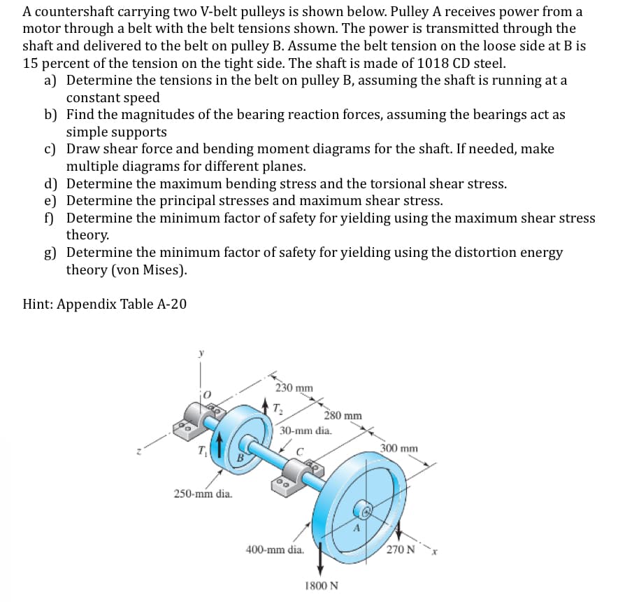
Transcribed Image Text:A countershaft carrying two V-belt pulleys is shown below. Pulley A receives power from a
motor through a belt with the belt tensions shown. The power is transmitted through the
shaft and delivered to the belt on pulley B. Assume the belt tension on the loose side at B is
15 percent of the tension on the tight side. The shaft is made of 1018 CD steel.
a) Determine the tensions in the belt on pulley B, assuming the shaft is running at a
constant speed
b) Find the magnitudes of the bearing reaction forces, assuming the bearings act as
simple supports
c) Draw shear force and bending moment diagrams for the shaft. If needed, make
multiple diagrams for different planes.
d) Determine the maximum bending stress and the torsional shear stress.
e) Determine the principal stresses and maximum shear stress.
f) Determine the minimum factor of safety for yielding using the maximum shear stress
theory.
g) Determine the minimum factor of safety for yielding using the distortion energy
theory (von Mises).
Hint: Appendix Table A-20
N
T₁
250-mm dia.
230 mm
T₂
280 mm
30-mm dia.
300 mm
400-mm dia.
1800 N
270 N
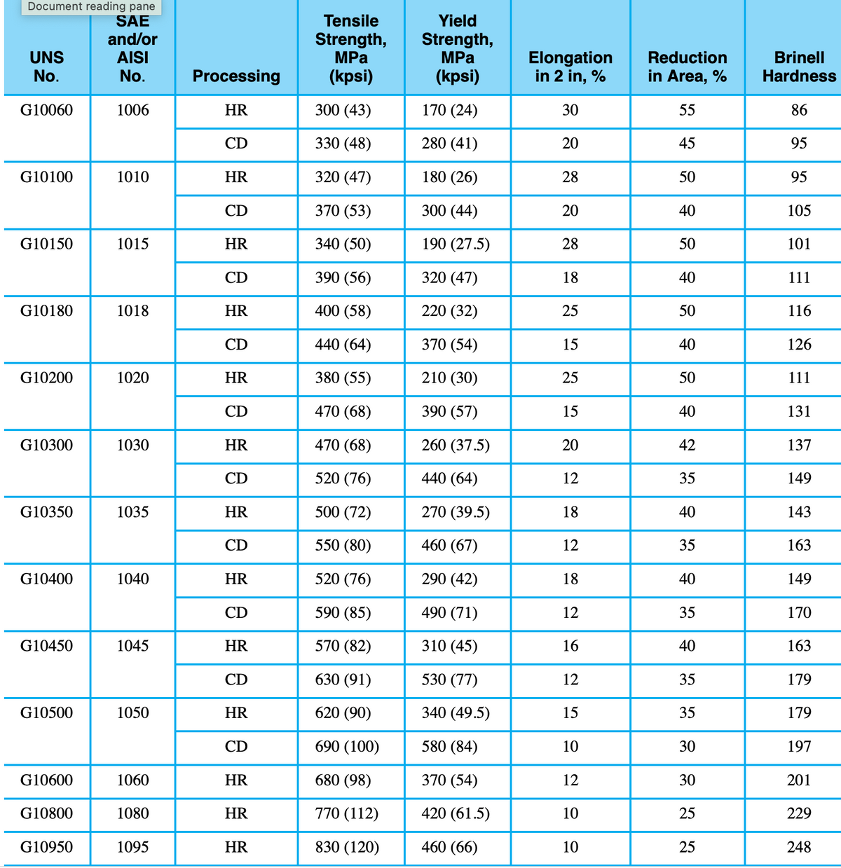
Transcribed Image Text:Document reading pane
SAE
and/or
UNS
AISI
No.
No.
Processing
Tensile
Strength,
MPa
(kpsi)
Yield
Strength,
MPa
Elongation
Reduction
(kpsi)
in 2 in, %
in Area, %
Brinell
Hardness
G10060
1006
HR
300 (43)
170 (24)
30
55
86
CD
330 (48)
280 (41)
20
45
95
G10100
1010
HR
320 (47)
180 (26)
28
50
95
CD
370 (53)
300 (44)
20
40
105
G10150
1015
HR
340 (50)
190 (27.5)
28
50
101
CD
390 (56)
320 (47)
18
40
111
G10180
1018
HR
400 (58)
220 (32)
25
50
116
CD
440 (64)
370 (54)
15
40
126
G10200
1020
HR
380 (55)
210 (30)
25
50
111
CD
470 (68)
390 (57)
15
40
131
G10300
1030
HR
470 (68)
260 (37.5)
20
42
137
CD
520 (76)
440 (64)
12
35
149
G10350
1035
HR
500 (72)
270 (39.5)
18
40
143
CD
550 (80)
460 (67)
12
35
163
G10400
1040
HR
520 (76)
290 (42)
18
40
149
CD
590 (85)
490 (71)
12
35
170
G10450
1045
HR
570 (82)
310 (45)
16
40
163
CD
630 (91)
530 (77)
12
35
179
G10500
1050
HR
620 (90)
340 (49.5)
15
35
179
CD
690 (100)
580 (84)
10
30
197
G10600
1060
HR
680 (98)
370 (54)
12
30
201
G10800
1080
HR
770 (112)
420 (61.5)
10
25
229
G10950
1095
HR
830 (120)
460 (66)
10
10
25
248
Expert Solution
This question has been solved!
Explore an expertly crafted, step-by-step solution for a thorough understanding of key concepts.

This is a popular solution!

Trending now
This is a popular solution!

Step by step
Solved in 2 steps with 4 images

Recommended textbooks for you
Mechanics of Materials (MindTap Course List)
Mechanical Engineering
ISBN:
9781337093347
Author:
Barry J. Goodno, James M. Gere
Publisher:
Cengage Learning
Mechanics of Materials (MindTap Course List)
Mechanical Engineering
ISBN:
9781337093347
Author:
Barry J. Goodno, James M. Gere
Publisher:
Cengage Learning