AutoSave ✓ W= Interference_172 - Saved to my Mac Search (Cmd + Ctrl + U) Comments Editing ✓ Share ✓ Home Insert Draw Design Layout References Mailings Review View Calibri ✓ 11 ✓ Aˆ A Aa PD ✓ E ✓ 会 [ AaBbCcDdEe AaBbCcDdEe Paste BI UV ab x² A A ✓ Normal No Spacing x AaBbCcDa Heading 1 AaBbCcDdE AaBb > Heading 2 Title Styles Dictate Sensitivity Add-ins Editor ✓ ✓ ✓ Pane Page 1 of 4 927 words English (United States) Wave Interference https://phet.colorado.edu/sims/html/wave-interference/latest/wave-interference_en.html In your lab report, be sure to show calculations. And include screenshots. Part 1. Double Slit Interference In the pictures on the last page, the rays are emitted in all directions from the slits, but let's concentrate on the rays that are emitted in a direction toward a distant screen (☐ measured from the normal to the barrier). One of these rays has further to travel to reach the screen, and the path difference is given by d sin□. Small angle simplification: If ☐ is small and (<< 1 rad), then sin(in at radians), bright spots occur 1 2 on the screen 0 = mo ; )o dark spots occur at □=(m+ d Ꮎ to screen d sin 0 As shown below, the angle ☐ (measured from the center of the screen) is related to the distance x measured on the screen by tan (□)=x/L, where L is the distance from the screen to the source of light (the aperture). aperture tan = x/L laser screen X www. Focus + 134% AutoSave ✓ Home Insert Draw Design Layout References Mailings Review Calibri ✓ 11 ✓ Aˆ A Aa PD ✓ E ✓ Paste BI UV ab x² A A ✓ W= Interference_172 - Saved to my Mac Search (Cmd + Ctrl + U) Comments Editing ✓ Share ✓ View Z↓ ་ AaBbCcDdEe AaBbCcDdEe Normal No Spacing x AaBbCcDa Heading 1 AaBbCcDdE AaBb > Heading 2 Title ✓ ✓ Styles Pane Dictate Sensitivity Add-ins Editor x L d m radians) so the locations of the interference bright spots are given by ☐ = = Procedures: A) Set the slit width to 500 nm and slit separation to 1500 nm. Record your slit separation d in Table 1. B) Press the green button on the light generator and generate an interference pattern on the screen. (Again, you should see something like what you see at the top of this page.) C) Pull the measuring tape tool out of the box in the upper right and use it to measure L (using 3500 nm to 4000 nm), the distance between the slits and the screen. Then measure x the distance from the center of the central bright spot to the center of one of the 1st order bright spots. Record these values in Table 1. (Be sure to include units!!!) D) Calculate the wavelength of the light λ using the diffraction formula derived in the Background section. Record this value in Table 1. E) Pause the simulation and use the measuring tape tool to measure the wavelength directly. Record this value in Table 1. F) Calculate the %-error between your calculated and measured values, and record this value in Table 1. G) Adjust the frequency of light and repeat steps B-F. Color of Light Slit Separation d Distance from Slits to Screen L Distance from Central to 1st Wavelength (calculated) Wavelength (measured) %-Error Order Bright Spot x Red 1500 nm 3676.3 nm 1792.9 731.5 696.5 4.87% Violet 1500 nm 3676.3 1056 430.9 410 4.85% Analysis: Page 2 of 4 927 words English (United States) Focus + 134%
AutoSave ✓ W= Interference_172 - Saved to my Mac Search (Cmd + Ctrl + U) Comments Editing ✓ Share ✓ Home Insert Draw Design Layout References Mailings Review View Calibri ✓ 11 ✓ Aˆ A Aa PD ✓ E ✓ 会 [ AaBbCcDdEe AaBbCcDdEe Paste BI UV ab x² A A ✓ Normal No Spacing x AaBbCcDa Heading 1 AaBbCcDdE AaBb > Heading 2 Title Styles Dictate Sensitivity Add-ins Editor ✓ ✓ ✓ Pane Page 1 of 4 927 words English (United States) Wave Interference https://phet.colorado.edu/sims/html/wave-interference/latest/wave-interference_en.html In your lab report, be sure to show calculations. And include screenshots. Part 1. Double Slit Interference In the pictures on the last page, the rays are emitted in all directions from the slits, but let's concentrate on the rays that are emitted in a direction toward a distant screen (☐ measured from the normal to the barrier). One of these rays has further to travel to reach the screen, and the path difference is given by d sin□. Small angle simplification: If ☐ is small and (<< 1 rad), then sin(in at radians), bright spots occur 1 2 on the screen 0 = mo ; )o dark spots occur at □=(m+ d Ꮎ to screen d sin 0 As shown below, the angle ☐ (measured from the center of the screen) is related to the distance x measured on the screen by tan (□)=x/L, where L is the distance from the screen to the source of light (the aperture). aperture tan = x/L laser screen X www. Focus + 134% AutoSave ✓ Home Insert Draw Design Layout References Mailings Review Calibri ✓ 11 ✓ Aˆ A Aa PD ✓ E ✓ Paste BI UV ab x² A A ✓ W= Interference_172 - Saved to my Mac Search (Cmd + Ctrl + U) Comments Editing ✓ Share ✓ View Z↓ ་ AaBbCcDdEe AaBbCcDdEe Normal No Spacing x AaBbCcDa Heading 1 AaBbCcDdE AaBb > Heading 2 Title ✓ ✓ Styles Pane Dictate Sensitivity Add-ins Editor x L d m radians) so the locations of the interference bright spots are given by ☐ = = Procedures: A) Set the slit width to 500 nm and slit separation to 1500 nm. Record your slit separation d in Table 1. B) Press the green button on the light generator and generate an interference pattern on the screen. (Again, you should see something like what you see at the top of this page.) C) Pull the measuring tape tool out of the box in the upper right and use it to measure L (using 3500 nm to 4000 nm), the distance between the slits and the screen. Then measure x the distance from the center of the central bright spot to the center of one of the 1st order bright spots. Record these values in Table 1. (Be sure to include units!!!) D) Calculate the wavelength of the light λ using the diffraction formula derived in the Background section. Record this value in Table 1. E) Pause the simulation and use the measuring tape tool to measure the wavelength directly. Record this value in Table 1. F) Calculate the %-error between your calculated and measured values, and record this value in Table 1. G) Adjust the frequency of light and repeat steps B-F. Color of Light Slit Separation d Distance from Slits to Screen L Distance from Central to 1st Wavelength (calculated) Wavelength (measured) %-Error Order Bright Spot x Red 1500 nm 3676.3 nm 1792.9 731.5 696.5 4.87% Violet 1500 nm 3676.3 1056 430.9 410 4.85% Analysis: Page 2 of 4 927 words English (United States) Focus + 134%

College Physics
11th Edition
ISBN:9781305952300
Author:Raymond A. Serway, Chris Vuille
Publisher:Raymond A. Serway, Chris Vuille
Chapter24: Wave Optics
Section: Chapter Questions
Problem 7P: Two radio antennas separated by d = 3.00 102 cm. as shown in Figure P24.7, simultaneously broadcast...

Related questions
Question
I am confused about how to answer these and the math
Transcribed Image Text:AutoSave
✓
W= Interference_172 - Saved to my Mac
Search (Cmd + Ctrl + U)
Comments
Editing ✓
Share ✓
Home Insert Draw
Design Layout References
Mailings Review
View
Calibri
✓ 11
✓
Aˆ A Aa PD
✓
E
✓
会
[
AaBbCcDdEe
AaBbCcDdEe
Paste
BI UV ab
x² A
A ✓
Normal
No Spacing
x AaBbCcDa
Heading 1
AaBbCcDdE AaBb
>
Heading 2
Title
Styles
Dictate Sensitivity Add-ins
Editor
✓
✓
✓
Pane
Page 1 of 4
927 words
English (United States)
Wave Interference
https://phet.colorado.edu/sims/html/wave-interference/latest/wave-interference_en.html
In your lab report, be sure to show calculations. And include screenshots.
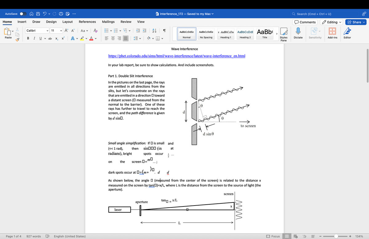
Part 1. Double Slit Interference
In the pictures on the last page, the rays
are emitted in all directions from the
slits, but let's concentrate on the rays
that are emitted in a direction toward
a distant screen (☐ measured from the
normal to the barrier). One of these
rays has further to travel to reach the
screen, and the path difference is given
by d sin□.
Small angle simplification: If ☐ is small and
(<< 1 rad), then
sin(in
at
radians), bright
spots
occur
1
2
on
the screen 0 =
mo
;
)o
dark spots occur at □=(m+
d
Ꮎ
to screen
d sin 0
As shown below, the angle ☐ (measured from the center of the screen) is related to the distance x
measured on the screen by tan (□)=x/L, where L is the distance from the screen to the source of light (the
aperture).
aperture
tan = x/L
laser
screen
X
www.
Focus
+
134%
Transcribed Image Text:AutoSave
✓
Home Insert Draw
Design Layout References
Mailings Review
Calibri
✓ 11
✓
Aˆ A Aa PD
✓
E
✓
Paste
BI UV ab
x² A
A ✓
W= Interference_172 - Saved to my Mac
Search (Cmd + Ctrl + U)
Comments
Editing ✓
Share ✓
View
Z↓
་
AaBbCcDdEe
AaBbCcDdEe
Normal
No Spacing
x AaBbCcDa
Heading 1
AaBbCcDdE AaBb
>
Heading 2
Title
✓
✓
Styles
Pane
Dictate Sensitivity Add-ins
Editor
x
L
d
m
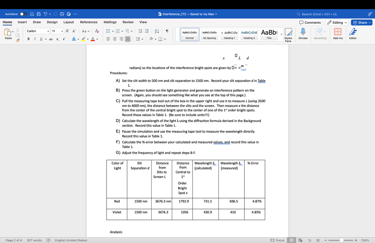
radians) so the locations of the interference bright spots are given by ☐ =
=
Procedures:
A) Set the slit width to 500 nm and slit separation to 1500 nm. Record your slit separation d in Table
1.
B) Press the green button on the light generator and generate an interference pattern on the
screen. (Again, you should see something like what you see at the top of this page.)
C) Pull the measuring tape tool out of the box in the upper right and use it to measure L (using 3500
nm to 4000 nm), the distance between the slits and the screen. Then measure x the distance
from the center of the central bright spot to the center of one of the 1st order bright spots.
Record these values in Table 1. (Be sure to include units!!!)
D) Calculate the wavelength of the light λ using the diffraction formula derived in the Background
section. Record this value in Table 1.
E) Pause the simulation and use the measuring tape tool to measure the wavelength directly.
Record this value in Table 1.
F) Calculate the %-error between your calculated and measured values, and record this value in
Table 1.
G) Adjust the frequency of light and repeat steps B-F.
Color of
Light
Slit
Separation d
Distance
from
Slits to
Screen L
Distance
from
Central to
1st
Wavelength
(calculated)
Wavelength
(measured)
%-Error
Order
Bright
Spot x
Red
1500 nm
3676.3 nm
1792.9
731.5
696.5
4.87%
Violet
1500 nm
3676.3
1056
430.9
410
4.85%
Analysis:
Page 2 of 4
927 words
English (United States)
Focus
+
134%
Expert Solution
This question has been solved!
Explore an expertly crafted, step-by-step solution for a thorough understanding of key concepts.

This is a popular solution!

Trending now
This is a popular solution!

Step by step
Solved in 2 steps with 4 images

Recommended textbooks for you
College Physics
Physics
ISBN:
9781305952300
Author:
Raymond A. Serway, Chris Vuille
Publisher:
Cengage Learning

College Physics
Physics
ISBN:
9781285737027
Author:
Raymond A. Serway, Chris Vuille
Publisher:
Cengage Learning

University Physics Volume 3
Physics
ISBN:
9781938168185
Author:
William Moebs, Jeff Sanny
Publisher:
OpenStax
College Physics
Physics
ISBN:
9781305952300
Author:
Raymond A. Serway, Chris Vuille
Publisher:
Cengage Learning
College Physics
Physics
ISBN:
9781285737027
Author:
Raymond A. Serway, Chris Vuille
Publisher:
Cengage Learning
University Physics Volume 3
Physics
ISBN:
9781938168185
Author:
William Moebs, Jeff Sanny
Publisher:
OpenStax


Glencoe Physics: Principles and Problems, Student…
Physics
ISBN:
9780078807213
Author:
Paul W. Zitzewitz
Publisher:
Glencoe/McGraw-Hill