
Elements Of Electromagnetics
7th Edition
ISBN: 9780190698614
Author: Sadiku, Matthew N. O.
Publisher: Oxford University Press
expand_more
expand_more
format_list_bulleted
Related questions
Question
my ID# is 016948724 please solve this problem step by step
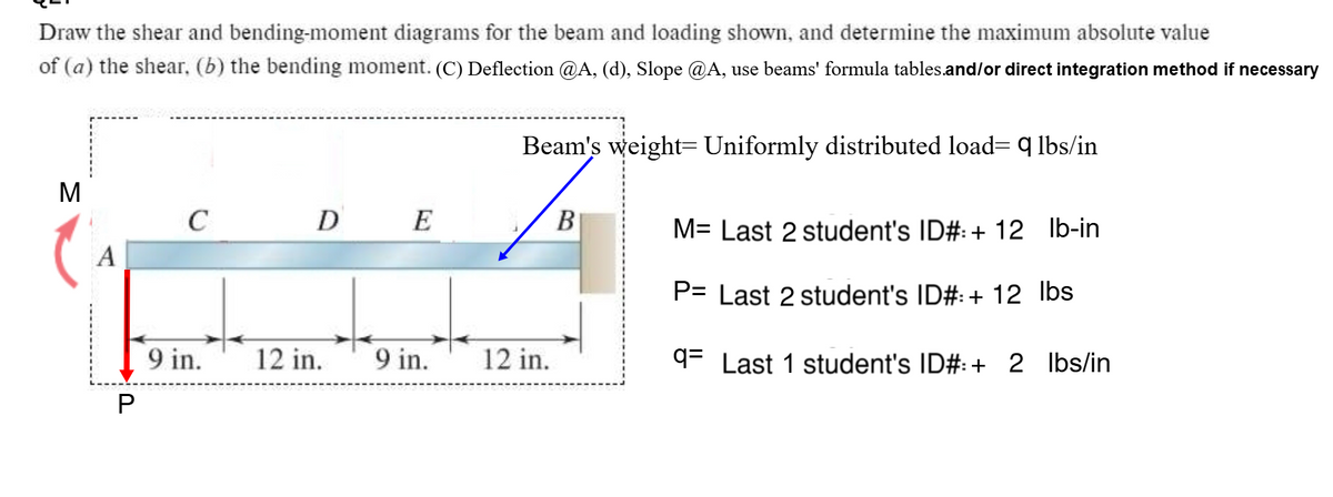

Transcribed Image Text:Draw the shear and bending-moment diagrams for the beam and loading shown, and determine the maximum absolute value
of (a) the shear, (b) the bending moment. (C) Deflection @A, (d), Slope @A, use beams' formula tables.and/or direct integration method if necessary
Beam's weight Uniformly distributed load= q lbs/in
M
C
D E
B
M= Last 2 student's ID#: + 12 lb-in
A
P= Last 2 student's ID#: + 12 lbs
9 in.
12 in. 9 in.
12 in.
q Last 1 student's ID#: + 2 lbs/in
P
Expert Solution
This question has been solved!
Explore an expertly crafted, step-by-step solution for a thorough understanding of key concepts.

Step by stepSolved in 2 steps with 3 images

Knowledge Booster

Similar questions
- Needs Complete typed solution with 100 % accuracy.arrow_forwardFor the simply supported beam subjected to the loading shown, derive equations for the shear force V and the bending moment M for any location in the beam. (Place the origin at point A.) Let a-3.25 m, b=4.75 m, Pg - 35kN, and Pc = 80kN. Construct the shear- force and bending-moment diagrams on paper and use the results to answer the questions in the subsequent parts of this GO exercise. A Ay- 58.66 - Dy- Calculate the reaction forces A, and Dy acting on the beam. Positive values for the reactions are indicated by the directions of the red arrows shown on the free-body diagram below. (Note: Since Ax = 0, it has been omitted from the free-body diagram.) Answers: a 56.33 (a) V= (b) V- (c) V- B i i PB B kN с kN C Determine the shear force acting at each of the following locations: (a) x-2m (b)x - 4 m (c) x-8 m Note that x = 0 at support A. When entering your answers, use the shear-force sign convention detailed in Section 7.2. 3 3 3 KN D b kN D ·x Dyarrow_forwardUse the graphical method to construct the shear-force and bending-moment diagrams for the beam shown. Let a = 2.8 m, b = 5.6 m, c = 3.8 m, P = 20 kN, w = 45 kN/m, and Q-10 kN. A P B W b C X What is the maximum bending moment on the beam? Answer in kN-m rounded-off to 2 decimal places When entering your answers, use the bending moment sign convention. Iarrow_forward
- from this problem a want you to help to draw the shear moment and the bending momentarrow_forwardUse the graphical method to construct the shear-force and bending-moment diagrams for the beam shown. Let a=11 ft, b=6 ft and w = 12 kips/ft.Calculate the reaction forces Ay and Cy acting on the beam. Positive values for the reactions are indicated by the directions of the red arrows shown on the free-body diagram below. (Note: Since Ax = 0, it has been omitted from the free-body diagram.)Answers: Ay = kips, Cy = kips.arrow_forwardUse the graphical method to construct the shear-force and bending-moment diagrams for the beam shown. Let a=4.0 ft, b=8.0 ft, c=4.0 ft, d=3.0 ft, w = 6.5 kips/ft and P = 45 kips. Construct the shear-force and bending-moment diagrams on paper and use the results to answer the questions in the subsequent parts of this GO exercise. a B a W B W C b d For this loading, calculate the reaction forces Ay and Ey acting on the beam. Positive values for the reactions are indicated by the directions of the red arrows shown on the free-body diagram below. (Note: Since Ax = 0, it has been omitted from the free-body diagram.) b C C P C D P Ľ E d E ·x Eyarrow_forward
- Part 1 For the simply supported beam subjected to the loading shown, derive equations for the shear force Vand the bending moment M for any location in the beam. (Place the origin at point A.) Let a-10.5 ft, b-24.0 ft, P- 20 kips and w - 5.5 kips/ft. Construct the shear-force and bending-moment diagrams on paper and use the results to answer the questions in the subsequent parts of this GO exercise. B Calculate the reaction forces Ay and Cy acting on the beam. Positive values for the reactions are indicated by the directions of the red arrows shown on the free-body diagram below. (Note: Since A, - 0, it has been omitted from the free-body diagram.) Answers: kips Cy- kips Part 2 Determine the shear force acting at each of the following locations: (a) x = 10.5-ft (i.e., just to the left of point B) (b) x = 10.5+ ft (i.e., just to the right of point B) (c) x = 32.5 ft Note that x-0 at support A. When entering your answers, use the shear-force sign convention detailed in Section 7.2.…arrow_forwardHi please assit in finding and plotting shear force diagram and bending moment diagram for the attached. please show all workingarrow_forwardUse the graphical method to construct the shear-force and bending-moment diagrams for the beam shown. Let a= 3.5 ft, b= 8.0 ft, t, c= 5.0 ft, d= 3.0 ft, w = 8.5 kips/ft and P = 54 kips. Construct the shear-force and bending-moment diagrams on paper and use the results to answer the questions in the subsequent parts of this GO exercise. P В D E b d For this loading, calculate the reaction forces A, and E, acting on the beam. Positive values for the reactions are indicated by the directions of the red arrows shown on the free-body diagram below. (Note: Since A = 0, it has been omitted from the free-body diagram.) P B C E b d E, Answers: Ay = i kips, Ey = i kips.arrow_forward
- I'm on my last attempt pls helparrow_forwardUse the graphical method to construct the shear-force and bending-moment diagrams for the beam shown. Let a=4.0 ft, b-8.0 ft, c-4.0 ft, d=3.0 ft, w = 6.5 kips/ft and P = 45 kips. Construct the shear-force and bending-moment diagrams on paper and use the results to answer the questions in the subsequent parts of this GO exercise. A a a B Part 2 b d For this loading, calculate the reaction forces Ay and Ey acting on the beam. Positive values for the reactions are indicated by the directions of the red arrows shown on the free-body diagram below. (Note: Since Ax = 0, it has been omitted from the free-body diagram.) Save for Later B W Answers: Ay = i 37.575 eTextbook and Media W AV=P₂ b C V₁ - V₁ = Sw(x) dx C C с D + D d kips, Ey= M₂ E i E ZA x Ey X Incorrect If your answer for part (a) or (e) is incorrect, recall that concentrated loads create discontinuities in the shear-force diagram. Refer to the table below (Construction Rules for Shear-Force and Bending-Moment Diagrams), Rule 1. At…arrow_forward1-What are the reactions at the pin and roller supports? (at A and B) 2- Give the (signed) values of the largest shear and bending moment occurring anywhere within the beam. (Vmax and Mmax)arrow_forward
arrow_back_ios
SEE MORE QUESTIONS
arrow_forward_ios
Recommended textbooks for you
- Elements Of ElectromagneticsMechanical EngineeringISBN:9780190698614Author:Sadiku, Matthew N. O.Publisher:Oxford University Press
 Mechanics of Materials (10th Edition)Mechanical EngineeringISBN:9780134319650Author:Russell C. HibbelerPublisher:PEARSON
 Thermodynamics: An Engineering ApproachMechanical EngineeringISBN:9781259822674Author:Yunus A. Cengel Dr., Michael A. BolesPublisher:McGraw-Hill Education
  Control Systems EngineeringMechanical EngineeringISBN:9781118170519Author:Norman S. NisePublisher:WILEY
 Mechanics of Materials (MindTap Course List)Mechanical EngineeringISBN:9781337093347Author:Barry J. Goodno, James M. GerePublisher:Cengage Learning
 Engineering Mechanics: StaticsMechanical EngineeringISBN:9781118807330Author:James L. Meriam, L. G. Kraige, J. N. BoltonPublisher:WILEY
Elements Of Electromagnetics
Mechanical Engineering
ISBN:9780190698614
Author:Sadiku, Matthew N. O.
Publisher:Oxford University Press
Mechanics of Materials (10th Edition)
Mechanical Engineering
ISBN:9780134319650
Author:Russell C. Hibbeler
Publisher:PEARSON
Thermodynamics: An Engineering Approach
Mechanical Engineering
ISBN:9781259822674
Author:Yunus A. Cengel Dr., Michael A. Boles
Publisher:McGraw-Hill Education
Control Systems Engineering
Mechanical Engineering
ISBN:9781118170519
Author:Norman S. Nise
Publisher:WILEY
Mechanics of Materials (MindTap Course List)
Mechanical Engineering
ISBN:9781337093347
Author:Barry J. Goodno, James M. Gere
Publisher:Cengage Learning
Engineering Mechanics: Statics
Mechanical Engineering
ISBN:9781118807330
Author:James L. Meriam, L. G. Kraige, J. N. Bolton
Publisher:WILEY