
Introductory Circuit Analysis (13th Edition)
13th Edition
ISBN: 9780133923605
Author: Robert L. Boylestad
Publisher: PEARSON
expand_more
expand_more
format_list_bulleted
Related questions
Question

Transcribed Image Text:V₂
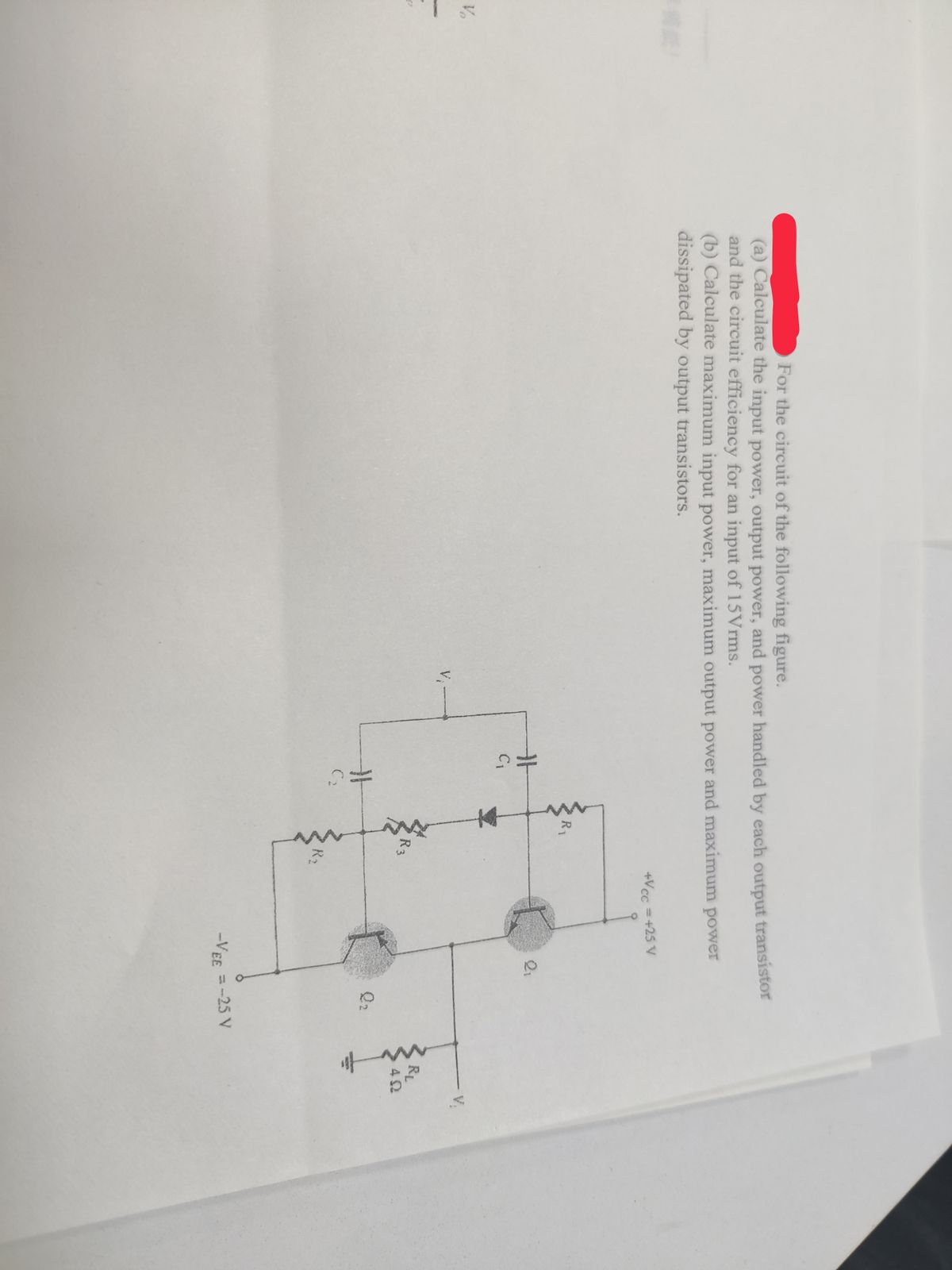
For the circuit of the following figure.
(a) Calculate the input power, output power, and power handled by each output transistor
and the circuit efficiency for an input of 15Vrms.
(b) Calculate maximum input power, maximum output power and maximum power
dissipated by output transistors.
H
C₁
H
C₂
R₁
R3
+Vcc = +25 V
2₁
Q₂
-VEE = -25 V
- V
RL
ΔΩ
to
Expert Solution
This question has been solved!
Explore an expertly crafted, step-by-step solution for a thorough understanding of key concepts.

This is a popular solution

Trending nowThis is a popular solution!

Step by stepSolved in 4 steps with 6 images

Knowledge Booster


Learn more about
Need a deep-dive on the concept behind this application? Look no further. Learn more about this topic, electrical-engineering and related others by exploring similar questions and additional content below.Similar questions
- Q3 Figure 3 shows the electric scheme of a specific current mirror circuit. (a) Which configuration of current mirror circuit is it? Determine the output resistance Rout of circuit in Figure 3. Show the details of calculation and state any assumption. (b) What is the main advantage of using a cascade current mirror over a simple current mirror made by only two transistors? (c) Iout M3 M2 M4 Vss =0 V Figure 3arrow_forward8.arrow_forwardplease quickly thanks !arrow_forward
- Please solve it.arrow_forwardQ3 Figure 3 shows two current mirrors based on MOSFET. Derive a formula relating the input current Iin to the output current Iout for the current mirror on the left of Figure 3 stating any assumption. (a) (b) Derive the input resistance Rin and output resistance Rout for the circuit on the left of Figure 3. State any assumption. (c) Derive a formula relating lin and Iout for the circuit on the right of Figure 3 assuming that M1 and M2 are identical, and that the length and width of the channel for the transistor M4 are double respect to those of M3. State anv assumption. VDD M3 M4 out Iout M1 M2 M1 M2 Vss = 0 V Vss = 0 V Figure 3arrow_forward
arrow_back_ios
arrow_forward_ios
Recommended textbooks for you
- Introductory Circuit Analysis (13th Edition)Electrical EngineeringISBN:9780133923605Author:Robert L. BoylestadPublisher:PEARSON
 Delmar's Standard Textbook Of ElectricityElectrical EngineeringISBN:9781337900348Author:Stephen L. HermanPublisher:Cengage Learning
 Programmable Logic ControllersElectrical EngineeringISBN:9780073373843Author:Frank D. PetruzellaPublisher:McGraw-Hill Education
  Fundamentals of Electric CircuitsElectrical EngineeringISBN:9780078028229Author:Charles K Alexander, Matthew SadikuPublisher:McGraw-Hill Education
 Electric Circuits. (11th Edition)Electrical EngineeringISBN:9780134746968Author:James W. Nilsson, Susan RiedelPublisher:PEARSON
 Engineering ElectromagneticsElectrical EngineeringISBN:9780078028151Author:Hayt, William H. (william Hart), Jr, BUCK, John A.Publisher:Mcgraw-hill Education,
Introductory Circuit Analysis (13th Edition)
Electrical Engineering
ISBN:9780133923605
Author:Robert L. Boylestad
Publisher:PEARSON
Delmar's Standard Textbook Of Electricity
Electrical Engineering
ISBN:9781337900348
Author:Stephen L. Herman
Publisher:Cengage Learning
Programmable Logic Controllers
Electrical Engineering
ISBN:9780073373843
Author:Frank D. Petruzella
Publisher:McGraw-Hill Education
Fundamentals of Electric Circuits
Electrical Engineering
ISBN:9780078028229
Author:Charles K Alexander, Matthew Sadiku
Publisher:McGraw-Hill Education
Electric Circuits. (11th Edition)
Electrical Engineering
ISBN:9780134746968
Author:James W. Nilsson, Susan Riedel
Publisher:PEARSON
Engineering Electromagnetics
Electrical Engineering
ISBN:9780078028151
Author:Hayt, William H. (william Hart), Jr, BUCK, John A.
Publisher:Mcgraw-hill Education,