Given a Bode diagram of a dynamic system, shown in Fig. 4: (a) Find the transfer function of the system G(s) (asymptotes are drawn for you and their slopes are indicated) T (b) Derive the open-loop system response to a harmonic input 2 cos 10t+- (c) Assuming a negative unity feedback configuration: Determine the gain and phase margins of the system Is the system closed-loop stable? Verify your answer using Nyquist plot (use software to generate Nyquist plot and explain how it confirms your conclusion of closed-loop stability/instability) (d) Assuming a proportional controller with gain Kp and negative unity feedback configuration: Can the system be destabilized by a finite gain proportional controller? If yes, find the gain K, that destabilizes the system. If not, explain why not. (e) Find Kp for the system to have a phase margin 20⁰ (f) What is the system phase margin when Kp = 10? At this value of Kp: What is the steady-state error of the closed-loop system to a step input of magnitude A? ● ● ● What is the steady-state error of the closed-loop system to a ramp input of magnitude A? NOTE: parts (b), (c), (e), (f) need to be solved graphically
Given a Bode diagram of a dynamic system, shown in Fig. 4: (a) Find the transfer function of the system G(s) (asymptotes are drawn for you and their slopes are indicated) T (b) Derive the open-loop system response to a harmonic input 2 cos 10t+- (c) Assuming a negative unity feedback configuration: Determine the gain and phase margins of the system Is the system closed-loop stable? Verify your answer using Nyquist plot (use software to generate Nyquist plot and explain how it confirms your conclusion of closed-loop stability/instability) (d) Assuming a proportional controller with gain Kp and negative unity feedback configuration: Can the system be destabilized by a finite gain proportional controller? If yes, find the gain K, that destabilizes the system. If not, explain why not. (e) Find Kp for the system to have a phase margin 20⁰ (f) What is the system phase margin when Kp = 10? At this value of Kp: What is the steady-state error of the closed-loop system to a step input of magnitude A? ● ● ● What is the steady-state error of the closed-loop system to a ramp input of magnitude A? NOTE: parts (b), (c), (e), (f) need to be solved graphically

Introductory Circuit Analysis (13th Edition)
13th Edition
ISBN:9780133923605
Author:Robert L. Boylestad
Publisher:Robert L. Boylestad
Chapter1: Introduction
Section: Chapter Questions
Problem 1P: Visit your local library (at school or home) and describe the extent to which it provides literature...

Related questions
Question
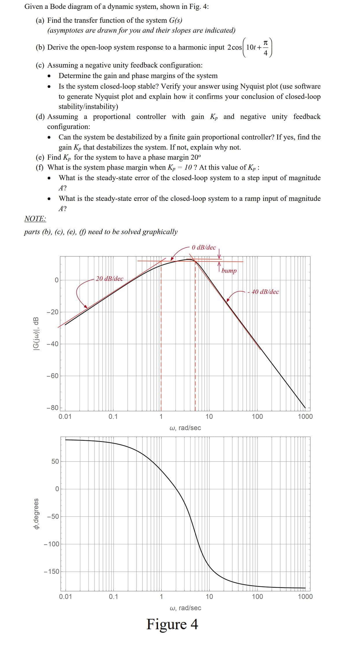
Transcribed Image Text:Given a Bode diagram of a dynamic system, shown in Fig. 4:
(a) Find the transfer function of the system G(s)
(asymptotes are drawn for you and their slopes are indicated)
(b) Derive the open-loop system response to a harmonic input 2 cos 10t+ 44
(c) Assuming a negative unity feedback configuration:
Determine the gain and phase margins of the system
Is the system closed-loop stable? Verify your answer using Nyquist plot (use software
to generate Nyquist plot and explain how it confirms your conclusion of closed-loop
stability/instability)
(d) Assuming a proportional controller with gain K₂ and negative unity feedback
configuration:
Can the system be destabilized by a finite gain proportional controller? If yes, find the
gain Kp that destabilizes the system. If not, explain why not.
(e) Find Kp for the system to have a phase margin 20⁰
(f) What is the system phase margin when K₂ = 10? At this value of Kp:
What is the steady-state error of the closed-loop system to a step input of magnitude
A?
|G(jw)|, dB
●
ø, degrees
●
NOTE:
parts (b), (c), (e), (f) need to be solved graphically
What is the steady-state error of the closed-loop system to a ramp input of magnitude
A?
0
-20
-40
-60
-80
0.01
50
0
-50
-100
-150
0.01
20 dB dec
0.1
0.1
1
1
0 dB/dec
w, rad/sec
w, rad/sec
Figure 4
10
10
↑hump
40 dB/dec
100
100
1000
1000
Expert Solution
This question has been solved!
Explore an expertly crafted, step-by-step solution for a thorough understanding of key concepts.

This is a popular solution!

Trending now
This is a popular solution!

Step by step
Solved in 9 steps with 3 images

Knowledge Booster


Learn more about
Need a deep-dive on the concept behind this application? Look no further. Learn more about this topic, electrical-engineering and related others by exploring similar questions and additional content below.Recommended textbooks for you
Introductory Circuit Analysis (13th Edition)
Electrical Engineering
ISBN:
9780133923605
Author:
Robert L. Boylestad
Publisher:
PEARSON

Delmar's Standard Textbook Of Electricity
Electrical Engineering
ISBN:
9781337900348
Author:
Stephen L. Herman
Publisher:
Cengage Learning

Programmable Logic Controllers
Electrical Engineering
ISBN:
9780073373843
Author:
Frank D. Petruzella
Publisher:
McGraw-Hill Education
Introductory Circuit Analysis (13th Edition)
Electrical Engineering
ISBN:
9780133923605
Author:
Robert L. Boylestad
Publisher:
PEARSON
Delmar's Standard Textbook Of Electricity
Electrical Engineering
ISBN:
9781337900348
Author:
Stephen L. Herman
Publisher:
Cengage Learning
Programmable Logic Controllers
Electrical Engineering
ISBN:
9780073373843
Author:
Frank D. Petruzella
Publisher:
McGraw-Hill Education

Fundamentals of Electric Circuits
Electrical Engineering
ISBN:
9780078028229
Author:
Charles K Alexander, Matthew Sadiku
Publisher:
McGraw-Hill Education

Electric Circuits. (11th Edition)
Electrical Engineering
ISBN:
9780134746968
Author:
James W. Nilsson, Susan Riedel
Publisher:
PEARSON

Engineering Electromagnetics
Electrical Engineering
ISBN:
9780078028151
Author:
Hayt, William H. (william Hart), Jr, BUCK, John A.
Publisher:
Mcgraw-hill Education,