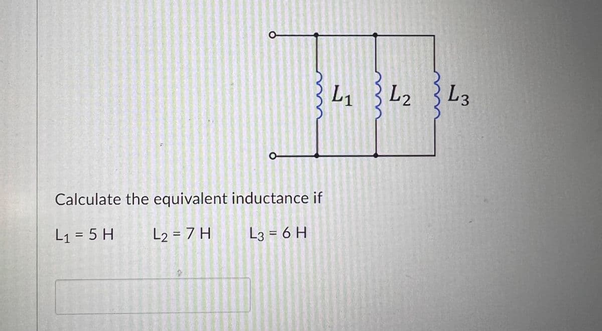
O о Calculate the equivalent inductance if L₁ = 5 H L₂ = 7 H L3=6 H L- L2 L3


Q: I need a handwritten expert solution and the correct and complete question prompt.
A: Z11=(5−j6)Ω Z12=5Ω Z21=5Ω Z22=(5+j8)ΩExplanation:Step 1:Step 2:
Q: Ex6(H.W): For the comparator circuit, if Vin (-) = 11 sin 75.36t, Vref (+) = 3 VDC, VCC=±12 V, draw…
A:
Q: III.B. Design a summing amplifier that will average five input voltages.
A: we need to design a summing amplifier that will average all five inputs.
Q: Show All work in the figure shown below determine if the following statement is correct based on…
A: TRUE is the required option.Explanation: In the loop 2 (I2 current), there is an independent current…
Q: Baffles are provided in heat exchangers to increase the a. Fouling factor b. Heat transfer area c.…
A: Baffles are provided in heat exchangers to increase the:b. Heat transfer areaBaffles are plates or…
Q: 4. For the circuit below, the switch has been in position x for a long time. At t = 0, the switch…
A:
Q: sketch vL1 and vR2 on a graph. mark the labels in microseconds one time constant after the charging…
A: The plots are shown below. Seperate and combined plots are show. Explanation:Step 1: finding…
Q: Design an RLC network which, when placed in parallel with a 100 (2% tolerance) resistor, yields an…
A: This is a RLC circuit
Q: 11. Find i(t) and V.(t) in the following circuit.
A: In this question, we need to determine the current iL(t) and voltage Vo(t) as shown in the…
Q: Electric Circuits/Two-port: I find all the coefficient values with an explanation of the steps to…
A: To find the coefficient values in a two-port electric circuit, start by determining the voltage gain…
Q: In the circuit in Fig. P7.29 the voltage and current expressions are Find a) R. b) C. v = 72e-500 V,…
A: “Since you have posted a question with multiple sub parts, we will provide the solution only to the…
Q: Figure P7.3 30 Ω w a t=0 + 60 V + 702V2 - 90 Ω w 0.32 HV1
A: (a) 0.5A (b) 0.002 sec (or) 2ms (C) i=0.5e−500tAv1=−80e−500tVv2=−35e−500tV (d)…
Q: Circuit Theory: I have this following circuit but its not producing the correct output. My input is…
A: Please refer below pages.If you have any doubts please feel free to ask.Explanation:Step 1: Step 2:…
Q: H.W: Determine Vo and ID for the circuit in figure below after adding a resistance of 2kQ in series…
A: The given circuit is We need to determine the values of Vo and ID for the circuit in the figure…
Q: i need help
A: I have attached the image below Explanation:
Q: 9.29. Determine whether the system described by -1 y[n]=kx[k + 1] is (a) memoryless; (b) causal; (c)…
A: Since you have posted a question with multiple subparts, we will provide the solution only to the…
Q: Oscilloscope The oscilloscope is an instrument that will display the variation of a voltage with…
A: According to the question, we need to explain the given theory of the oscilloscope.
Q: 4. For circuit-4, use Mesh analysis to find (a) the current through all the branches, (b) the power…
A: The given circuit isR11=33.5 Ω.We need to determinea. The current through each branch.b. The power…
Q: A pure sinusoidal waveform with a period time or 0.02, has a frequency of 50Hz, define the angular…
A: The objective of the question is to calculate the angular frequency of a sinusoidal waveform given…
Q: 2. Obtain the equivalent resistance at the terminals a-b for the given circuit.
A: The given data is shown below:
Q: A band-limited signal with a maximum frequency of 5 kHz is to be sampled. According to the sampling…
A: The given data is shown below:Bandlimited signal with a maximum frequency of up to 5kHz is to be…
Q: Electric Circuits/Two-port: I find all the coefficient values with an explanation of the steps to…
A: y12 should be = -1/6.see the attachment for details.Explanation:
Q: Two point charges are located at a distance a from the z = 0 plane along the z-axis. Calculate the…
A: see belowExplanation:and Thanks Any problem please ask
Q: D E a Eulerize this graph in an efficient way, then find an Euler circuit on the eulerized graph. Gi…
A: This is a eular Circuit
Q: an active high pass filter with a specified. Design break frequency of 100 krad/sec and a Passband…
A: The design specifications of an active high-pass filter are given as:break or corner frequency…
Q: 1. Solve for the complex Power delivered to the Source.
A:
Q: *4.35 Draw the Direct Form II realization of the LTI system d²x dx +2 dt +3y(t)=4 +5 d12 +6x(t). dt
A: The LTI system,
Q: 3. Find Vs if V = 8445°V. w 20 12 Vs |+ j20 ele HH -j292 V1 20 w Vo
A: The supply voltage Vs for the given circuit has been calculated. A detail explanation has been given…
Q: i need help
A: I have attached the image below Explanation:
Q: Obtain the transfer function Eo(s)/E(s) of the operational-amplifier circuit shown in Figure 6-91.…
A:
Q: 3.21 Determine v(t) in the circuit of Fig. P3.21 given that Us(t) = 2u(t) V, R₁ = 12, R2 = 32, C =…
A:
Q: For electric field E = Eoei(kr-wt) (where Eo 1 k), and hence B =kx E, show that the time- T-00 H') =…
A:
Q: A separately excited DC motor when from 200 a ✓ Source drives a load while running at 2000 RPM. When…
A: Torque is directly proportional to field current and armature current.Back emf is directly…
Q: In a medium characterized by μ= μ₁, ε = ε,ε a plane electromagnetic wave has an electric field given…
A:
Q: 2 A lossless transmission line of electrical length = 0.32 is terminated with a complex load…
A:
Q: 2. Find the inverse Laplace Transforms for the following: 2 3.5 a. F(s) = ++ (s+10)(s+10) (s+2) b.…
A: In this question, we need to determine the inverse Laplace transform. We solve this problem using…
Q: Part A In the figure, the total resistance is 14.6 ks, and the battery's emf is 28.4 V. If the time…
A: An RC series circuit is a circuit that contains a resistor (R) and a capacitor (C) connected in…
Q: A coil with a resistance 25 Q is connected in direct measurement mode of Q-meter. Resonance occurs…
A: The given data is shown below:
Q: Calculate V and ix in the circuit below.
A: In this question, we need to choose the correct option. What is Voltage V and current Ix as shown…
Q: H.W: Design Op-Amp circuit to give the following output using 4 op-amp or less. Vo= - - 2V₁ - 6V2 -…
A: This question is based on design .Opamp circuit
Q: For certain dynamometer ammeter, the mutual inductance M varies with deflection (expressed in…
A: The given data is shown below:
Q: Q3 5 Ω 2.5 Ω www www 2A(1 ΣΩ 10 Ω a www 23 10 Ω 1 A www (a) Find the Thevenin Equivalent between a…
A: Given:a circuit,we need to find:Thevenin equivalent between terminals a and b.
Q: Determine the maximum standard size fusefor the primary of a transformer with aprimary current of…
A: The primary-only protection method for a transformer involves selecting a fuse based on the primary…
Q: ssertion: In an AC, only capacitor circuit has instantaneous power equal to zero at any instant of…
A: Given that, Assertion: In an AC, only capacitor circuit has instantaneous power equal to zero at any…
Q: 1. a) Use node-voltage method to find v₁, v₂ and v3 in the circuit shown in below. b) How much power…
A: Kirchhoff's Current Law (KCL) is a fundamental principle in electrical engineering that states that…
Q: For the following circuit, initial conditions are as follows: Current across the inductor i L (0) =…
A:
Q: An ideal p+n step junction diode is switched with a current pusle from I = 0 to I= 1mA at t=0.…
A:
Q: Design an active high pass filter with a specified Passband break frequency of 1.100 rad/sec and a…
A: For specified break frequency and passband of 100rad/sec & 22 respectively. the active high pass…
Q: For the following open loop transfer function 2K G(s) = s(s+3) design a PD controller K₂+ KDS such…
A: Please go through the below answerExplanation:
Q: For the following system, accurately hand sketch the root locus and identify the following…
A:


Trending now
This is a popular solution!

Step by step
Solved in 1 steps with 5 images

- Capacitive Circuits Fill in all the missing values. Refer to the formulas that follow. XC=12fCC=12fXCf=12CXc Capacitance XC Frequency 38 F 60 Hz 78.8 400 Hz 250 pF 4.5 k 234 F 10 kHZ 240 50 Hz 10 F 36.8 560 nF 2 MHz 15 k 60 Hz 75 nF 560 470 pF 200 kHz 6.8 k 400 Hz 34 F 450Assume the circuit in Figure 21-1 has a power factor of 68%, an apparent power of 300 VA, and a frequency of 400 Hz. The capacitor has a capacitance of 4.7125 F. Find the missing values. ET ER EC IT IR IC Z R XC VA300 P VARSC PF68 C4.7125FThe circuit in Figure 24-2 is connected to a 120-V, 60-Hz line. The resistor has a resistance of 36 , the inductor has an inductive reactance of 40 , and the capacitor has a capacitive reactance of 50 . ET120VITZVAPFERIRR36PELILXL40VARsLLECICXC50VARsCC
- Assume the circuit shown in Figure 21-1 has an apparent power of 432 VA and a true power of 345.6 W. The capacitor has a capacitance of 15.8919 F, and the frequency is 60 Hz. Find the missing values. ET ER EC IT IR IC Z R XC VA432 P345.6W VARSC PF C15.8919FIncandescent lighting of 500 W is connected in parallel with an inductive load. A clamp-on ammeter reveals a total circuit current of 7 A. What is the inductance of the load connected in parallel with the incandescent lights? Assume a voltage of 120 V and a frequency of 60 Hz.What is the minimum AC voltage rating of each capacitor in Question 11?
- Two capacitors having values of 80 F and 60 F are connected in series. What is the total capacitance?A postage stamp mica capacitor has the following color marks starting at the upper left dot: yellow, violet, brown, green, no color, and blue. What are the capacitance value, tolerance, and voltage rating of this capacitor?A 15-F AC capacitor is connected in series with a 50 resistor. The capacitor has a voltage rating of 600 WVDC. The capacitor and resistor are connected to a 480-V, 60-Hz circuit. Is the voltage rating of the capacitor sufficient for this connection?
- Three capacitors having values of 2.2 F, 280 F, and 470 pF are connected in parallel. What is the total capacitance?An R-L series circuit contains two resistors and two inductors. The resistors dissipate powers of 96 watts and 125 watts. The inductors have reactive powers of 100 VARs and 78 VARs. What is the power factor?The circuit in Figure 24-2 is connected to a 60-Hz line. The apparent power in the circuit is 48.106 VA. The resistor has a resistance of 12 . The inductor has an inductive reactance of 60 , and the capacitor has a capacitive reactance of 45 . ETITZVA48.106PFERIRR12PELILXL60VARsLLECICXC45VARsCC
