P6.8. Time-domain analysis of a transmission-line system using the bounce-diagram technique. In the system shown in Fig. 6.67, the switch S is closed at t = 0. As- sume V(t) to be a direct voltage of 90 V and draw the voltage and current bounce diagrams. From these bounce diagrams, sketch: (a) the line voltage and line current versus t (up to t = 7.25 μs) at z = 0, z = 1, and z = 1/2; and (b) the line voltage and line current versus z for t = 1.2 μs and t = 3.5 µs. FIGURE 6.67 For Problem P6.8. 90 Ω V₂(t) t=0 z=0 Ζο = 60 Ω T = 1 μs 180 Ω z=1 www
P6.8. Time-domain analysis of a transmission-line system using the bounce-diagram technique. In the system shown in Fig. 6.67, the switch S is closed at t = 0. As- sume V(t) to be a direct voltage of 90 V and draw the voltage and current bounce diagrams. From these bounce diagrams, sketch: (a) the line voltage and line current versus t (up to t = 7.25 μs) at z = 0, z = 1, and z = 1/2; and (b) the line voltage and line current versus z for t = 1.2 μs and t = 3.5 µs. FIGURE 6.67 For Problem P6.8. 90 Ω V₂(t) t=0 z=0 Ζο = 60 Ω T = 1 μs 180 Ω z=1 www

Introductory Circuit Analysis (13th Edition)
13th Edition
ISBN:9780133923605
Author:Robert L. Boylestad
Publisher:Robert L. Boylestad
Chapter1: Introduction
Section: Chapter Questions
Problem 1P: Visit your local library (at school or home) and describe the extent to which it provides literature...

Related questions
Question
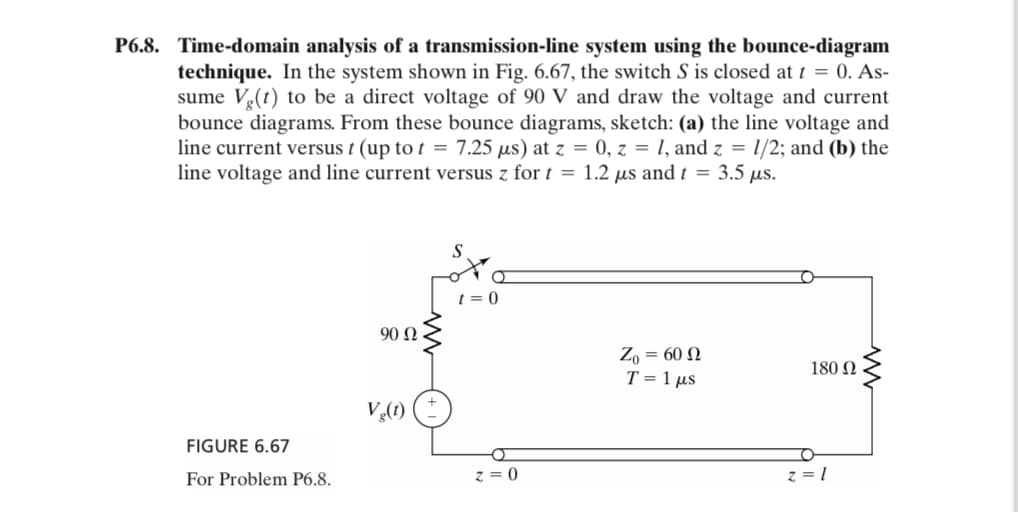
Transcribed Image Text:P6.8. Time-domain analysis of a transmission-line system using the bounce-diagram
technique. In the system shown in Fig. 6.67, the switch S is closed at t = 0. As-
sume V(t) to be a direct voltage of 90 V and draw the voltage and current
bounce diagrams. From these bounce diagrams, sketch: (a) the line voltage and
line current versus t (up to t = 7.25 μs) at z = 0, z = 1, and z = 1/2; and (b) the
line voltage and line current versus z for t = 1.2 μs and t = 3.5 µs.
FIGURE 6.67
For Problem P6.8.
90 Ω
V₂(t)
t=0
z=0
Ζο = 60 Ω
T = 1 μs
180 Ω
z=1
www
Expert Solution
This question has been solved!
Explore an expertly crafted, step-by-step solution for a thorough understanding of key concepts.

This is a popular solution!

Trending now
This is a popular solution!

Step by step
Solved in 2 steps with 1 images

Recommended textbooks for you
Introductory Circuit Analysis (13th Edition)
Electrical Engineering
ISBN:
9780133923605
Author:
Robert L. Boylestad
Publisher:
PEARSON

Delmar's Standard Textbook Of Electricity
Electrical Engineering
ISBN:
9781337900348
Author:
Stephen L. Herman
Publisher:
Cengage Learning

Programmable Logic Controllers
Electrical Engineering
ISBN:
9780073373843
Author:
Frank D. Petruzella
Publisher:
McGraw-Hill Education
Introductory Circuit Analysis (13th Edition)
Electrical Engineering
ISBN:
9780133923605
Author:
Robert L. Boylestad
Publisher:
PEARSON
Delmar's Standard Textbook Of Electricity
Electrical Engineering
ISBN:
9781337900348
Author:
Stephen L. Herman
Publisher:
Cengage Learning
Programmable Logic Controllers
Electrical Engineering
ISBN:
9780073373843
Author:
Frank D. Petruzella
Publisher:
McGraw-Hill Education

Fundamentals of Electric Circuits
Electrical Engineering
ISBN:
9780078028229
Author:
Charles K Alexander, Matthew Sadiku
Publisher:
McGraw-Hill Education

Electric Circuits. (11th Edition)
Electrical Engineering
ISBN:
9780134746968
Author:
James W. Nilsson, Susan Riedel
Publisher:
PEARSON

Engineering Electromagnetics
Electrical Engineering
ISBN:
9780078028151
Author:
Hayt, William H. (william Hart), Jr, BUCK, John A.
Publisher:
Mcgraw-hill Education,