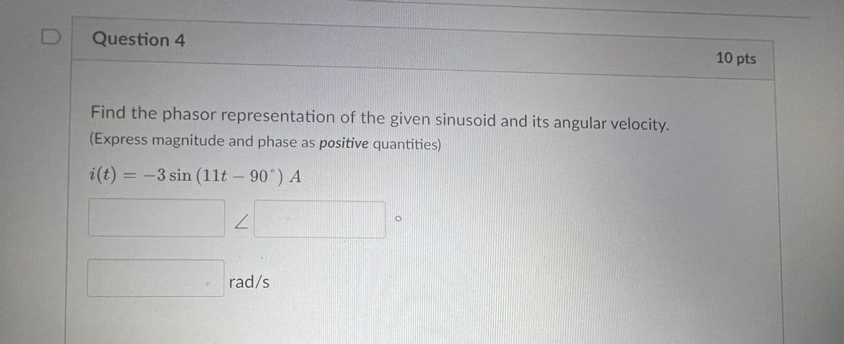
Question 4 Find the phasor representation of the given sinusoid and its angular velocity. (Express magnitude and phase as positive quantities) i(t) = -3 sin (11t - 90°) A L rad/s 10 pts


Q: 3. Find Find Reg. 40 ww Rog => 360 30 На H ww 3.P www 32 5.0 G Reg -10.52
A: Question 3:Given that, Equivalent resistance Req =?Note:By bartleby…
Q: Figure £7.9 E7,10 Find i(r) for t > 0 in Fig. E7.10 using the step-by-step method. 1-0 oto 12 V…
A: To determine io(t) for t>0 og given figure
Q: Show All work in the figure shown below determine if the following statement is correct based on…
A: TRUE is the required option.Explanation: In the loop 2 (I2 current), there is an independent current…
Q: EXAMPLE 4.6 A series circuit has R=492 and L=0.01 H Find the impedance at 100 Hz and 500 Hz.
A: The given data is shown below:
Q: Ex6(H.W): For the comparator circuit, if Vin (-) = 11 sin 75.36t, Vref (+) = 3 VDC, VCC=±12 V, draw…
A:
Q: Electric Circuits/Two-port: I find all the coefficient values with an explanation of the steps to…
A: I2=−0.07142857A V2=0.142857142V I1=0.892857142A In case of Doubts please do let me know…
Q: Ex// sketch the root-locus plot of, Consider the negative feedback system shown in Figure for this…
A: A unity negative feedback system is given by⇒G(s)=K(s+2)s2+2s+3;⇒H(s)=1.We need to sketch the root…
Q: Three loads, each with resistance 40Ω , are star connected to a 363.73V , 3-phase supply. a)…
A: The objective of the question is to determine the phase voltage, phase current, and line current of…
Q: Consider a system with frequency response of H (jw) jw+2 (jw+1)(jw+3) and suppose that the input to…
A: The given data is shown below:
Q: Needs Complete typed solution with 100 % accuracy.
A: Given that, a)…
Q: A three phase full bridge inverter operating in 180 degree conduction mode has a Y connected…
A: (d) 2.025 AExplanation:
Q: Circuit Theory: I have this following circuit but its not producing the correct output. My input is…
A: Please refer below pages.If you have any doubts please feel free to ask.Explanation:Step 1: Step 2:…
Q: H.W: Derive the following and draw the circuit. ⚫ The output voltage of the summation Op-Amp. ⚫ The…
A: In the given question we need to derive the output voltage expression of summation and subtractor…
Q: H.W: Design Op-Amp circuit to give the following output using 4 op-amp or less. Vo= - - 2V₁ - 6V2 -…
A: This question is based on design .Opamp circuit
Q: switch in position 1, the circuit will charge the inductor determine the thevenin equivalent…
A: The given circuit is: the circuit will charge the inductor determine the thevenin equivalent…
Q: An 820 Q resistance with an accuracy of ± 10% carries a current of 10 mA. The current was measured…
A:
Q: Given the plant transfer function G(s) = $²+9s+20 s3+6s²+11s+6 1) The state equation in diagonal…
A: The plant transfer transfer function of a system is⇒G(s)=s2+9s+20s3+6s2+11s+6 ;We need to find the…
Q: Using the format approach, write the nodal equations for the networks in Figure. Using determinants,…
A: KCL: The algebraic sum of all currents at a node is equal to zero. Kirchhoff's current law is…
Q: In the circuit in Fig. P7.29 the voltage and current expressions are Find a) R. b) C. v = 72e-500 V,…
A: “Since you have posted a question with multiple sub parts, we will provide the solution only to the…
Q: i need help thank you
A: Please refer below pages.If you have any doubts please feel free to ask.Explanation:Step 1: Step 2:…
Q: A household with electric resistance heating plans to switch from resistive heating to a ground…
A: To calculate the annual savings after switching from resistive heating to a ground source heat pump,…
Q: Question 2 = : Solve the below circuit using the Mesh-Current Method for R₁ = R2 = R3 = R4 = R5 R6…
A:
Q: + V1- 11 12 V2+ 1ΚΩ 1ΚΩ 13 5V 1ΚΩ + V3 + V4 . a) Write down Kirchoff Current Law (KCL) equations! b)…
A:
Q: i need help
A: I have attached the image below Explanation:
Q: A small region of an impure silicon crystal with dimensions. 1.25 × 10-6 mx 10-3 m x 10-3 m has only…
A: The given data is shown below:
Q: Determine the characteristics of the circuit below. Show your work! Parameter Value IB Ic IE VB V VE…
A: Given that,Redraw the circuit as shown below.
Q: Currents first equal. Switch S in the figure below is closed for time t < 0 and is opened at t = 0.…
A: According to the question, for the given circuit as shown belowWhen switch is open, we need to…
Q: A circuit is given according to the diagram below a) Calculate R1 b) Calculate I2 c) Calculate R2 d)…
A: Solved below .Explanation:
Q: Please help with practice problem. Please explain clearly the steps so I can study.
A: Please refer below pages.If you have any doubts please feel free to ask.Explanation:Step 1: Step 2:…
Q: 7.23 The switch in the circuit in Fig. P7.23 has been in the left position for a long time. Att = 0…
A: The solution is given below Explanation: If you are having doubt in any step please comment…
Q: O Amplifier O Oscilloscope O Actuator O Bandwidth can measure sound by converting that sound into…
A: The device that measures the sound needs to be identified from the given options.
Q: The figure shows two closed paths wrapped around two conducting loops carrying currents i₁ = 6.4 A…
A:
Q: Two 2-port networks with following parameters are connected in series. Z – parameters of network - 1…
A: The given data is shown below:Z-parameters of network-1Y-parameters of network-2
Q: 9) Consider the following circuit with A, CLK input waveforms. The sequence at the Q (Q1Q3Q2Q1Qo,…
A: Given:we need to find:output sequence Q4Q3Q2Q1Q0 for the given input and clock.
Q: A DC motor is initially at rest and is then connected to a 12V battery. The motor has aresistance of…
A: The objective of the question is to determine the current through the motor as a function of time,…
Q: Find the potential of point a with respect to point b in the figure. Express your answer using two…
A: Given:we need to find:a) potential of point a with respect to point b. b) magnitude of current…
Q: Please solve all showing all the steps in detail
A: (a) A = 0.9676+j0.00324B = 7.2+j72 ohmC = (-1.458+j885.82)*10-6 mhoD = 0.9676+j0.00324 (b) % Eff =…
Q: "*" 15 Ω ww 19.1 mH m 21.22 με 카 N "e" e=250 Sinot + 100 Sin 3ot+45 Sin 5ot+ 15 Sin 7ot+.......…
A: a.) The fundamental frequency of the supply is (ω).b.) The amplitude of this current component is 15…
Q: Q3 5 Ω 2.5 Ω www www 2A(1 ΣΩ 10 Ω a www 23 10 Ω 1 A www (a) Find the Thevenin Equivalent between a…
A: Given:a circuit,we need to find:Thevenin equivalent between terminals a and b.
Q: Find f(t) for each of the following functions. 280 a) F(s) = s²+14s +245 -s²+52s + 445 b) F(s) = c)…
A: “Since you have posted a question with multiple sub parts, we will provide the solution only to the…
Q: A DC motor with a starter is shown in Figure 2. Vs (± R₁ R2 R3 M Figure 2: DC Motor Starter (a) What…
A: The DC motor with a starter is shown below,
Q: Figure P8.5 shows open-loop poles and zeros. There are two possibilities for the sketch of the root…
A:
Q: Figure E26.26 2.00 10.00 V ww a 3.00 Ω 1.00 5.00 V 4.00 Ω b wwww 10.00 Ω www 26.27 The 10.00 V…
A: The circuit diagarm,
Q: Problem 6: Please find Vo and io. 2 ΚΩ w 5 ΚΩ 3 V 1 + www 8 ΚΩ w Va Vb 10 ΚΩ W + io + Vo 4 ΚΩ
A: The output voltage V0 and current output Current i0 have been calculated . A detail explanation has…
Q: draw a three-phase transformer equivalent circuit and also explain how formulas were derived
A: This is a 3 phase transformer equ6 circuit.
Q: a)use matlab to obtain the plot of i(t) vs t,over -pi <=t<=3pi. b) determine the values of i…
A: Detailed solution for waht it has been asked given below. Concept used: The unit step function is…
Q: A series RLC circuit consists of a 40 2 resistor, a 2.6 mH inductor, and a 610 nF capacitor. It is…
A:
Q: Use the mesh-current method to find the branch currents 1-16 in the circuit shown in (Figure 1).…
A:
Q: Design K that stabilizes the closed Loop system for K is constant (paregain) R(S) 5 S45-2
A:
Q: Chemical Engineering Don't copy Multiple dislikes will be given A 3 phase machine has 4 poles, 9…
A: A 3-phase machine has 4 poles, 9 slots per pole and 4 conductors 4 per slot arranged in two layer…


Trending now
This is a popular solution!

Step by step
Solved in 1 steps with 1 images

- What is the product of two complex numbers 4 + 3j and 2+ 2j where j = sqrt (1-) in phasor notation? Write the answer in the form, to make it easy to type, magnitude AT angle in radians.Find the phase relations for the following pairs of sinusoids. Sketch the curve e and i anddetermine which one LAGS and LEADS.a. v = 60 sin(377 t + 50°) V ; i = 3 sin(754t − 10°)A b. v = 6.4 sin(7.1 πt + 30°) V ; i = 7.3 sin(7.1 πt − 10°)A c. v = 42.3 sin(400 t + 60°) V ; i = −4.1 sin(400t − 50°)AEx. 1844. Given a sinusoidal voltage source in series with R,L, and C. The sinusoidal voltage source has a frequency of 600 Hz. R=5 Ohms, L=2 milliHenry, C=4 microFarad, V=20sin(wt) volts. Solve for the capacitor steady-state phasor current and voltage. I(jw)=Aexp(jB), vc(jw)=Dexp(jE), IMPORTANT RESTRICTION: Express radian angles between [-pi/2,pi/2]. Solve for the capacitor steady-state time-domain current and voltage: i(t)=Fsin(wt+G), vc(t)=Hsin(wt+K) Ans: w,A,B,D,E,F,G,H,K all MKS units. ans:9
- Ex. 1844. Given a sinusoidal voltage source in series with R,L, and C. The sinusoidal voltage source has a frequency of 500 Hz. R=7 Ohms, L=8 milliHenry, C=6 microFarad, V=20sin(wt) volts. Solve for the capacitor steady-state phasor current and voltage. I(jw)=Aexp(jB), vc(jw)=Dexp(jE), Express radian angles between [-pi/2,pi/2]. Solve for the capacitor steady-state time-domain current and voltage: i(t)=Fsin(wt+G), vc(t)=Hsin(wt+K) Ans: w,A,B,D,E,F,G,H,K all MKS units. ans:9Find the phase relation for the following pairs of sinusoids, (which leads and lags which by how much). Draw the phasor diagram e1= -20sqrt2 sin(377t + 200°) V e2 = -10sqrt2 sin(377t - 285°) VThe following phasor diagram is: a. The phasor diagram of SG when it is running at lagging power factor b. The phasor diagram of SM when it is running at leading power factor c. The phasor diagram of SM when it is running at lagging power factor with the existence of RA d. The phasor diagram of IM when it is running at lagging power factor
- Two alternating voltages are given by: v1 = 120 sin (ωt) volts and v2 =200 sin (ωt −π/4) volts. Obtain sinusoidal expressions for v1 −v2 (a) by plotting waveforms, (b) by resolution of phasors.If the rms phasor voltage is given as V angle= 60-degree, then how v(t) can be written.If y1=20 cos (ωt − 30°) and y2=40 cos (ωt + 60°), express y=y1 + y2 as asingle sinusoidal function.1. Solve by using trigonometric identities.2. Solve by using the phasor concept.