Use D-type flip-flops and gates to design a counter with the following repeated binary sequence: 0, 2, 1,3, 4, 6, 5,7.
Use D-type flip-flops and gates to design a counter with the following repeated binary sequence: 0, 2, 1,3, 4, 6, 5,7.

Chapter22: Sequence Control
Section: Chapter Questions
Problem 6SQ: Draw a symbol for a solid-state logic element AND.

Related questions
Question
6-16
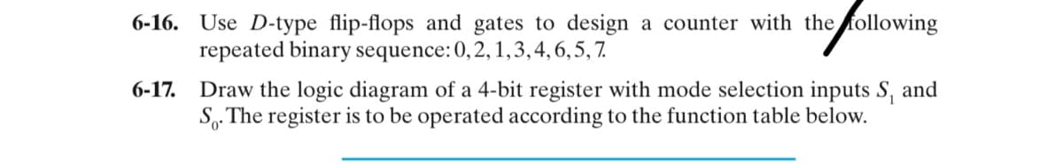
Transcribed Image Text:6-16. Use D-type flip-flops and gates to design a counter with the following
repeated binary sequence: 0, 2, 1,3, 4, 6, 5, 7.
6-17. Draw the logic diagram of a 4-bit register with mode selection inputs S, and
S. The register is to be operated according to the function table below.
Expert Solution
This question has been solved!
Explore an expertly crafted, step-by-step solution for a thorough understanding of key concepts.

This is a popular solution!

Trending now
This is a popular solution!

Step by step
Solved in 5 steps with 4 images

Knowledge Booster


Learn more about
Need a deep-dive on the concept behind this application? Look no further. Learn more about this topic, electrical-engineering and related others by exploring similar questions and additional content below.Recommended textbooks for you