name of the sensor - in the case of the Thermistor, you should return the "Thermistor" string and in the case of Light Sensor, you should return the "Light Sensor" string. The read method should read the analog signal specified by pin using the analogRead function and then convert that ADC value to a float value appropriate for that sensor. For the thermistor, you can use the code from the previous labs to convert the ADC value into the Fahrenheit temperature. Since the ADC on the Arduino is 10-bit instead of 8-bit, which is what we were getting over the serial port, you will need to adjust the ADC to voltage calculations appropriately. For the photoresistor, you will need to convert the ADC value into a light intensity. As the light level changes, the resistance of the photoresistor (Rp) will change - specifically, the resistance changes according to the following formula: R₂ = R₁ where L is the light intensity. In other words, RP is inversely proportional to L. The analog voltage that you will be measuring is given by the voltage divider formula Vana-R+1Kn where Vana is the analog voltage. As with the thermistor, you will need to convert the ADC value that you get from analogRead into a voltage. Once you get the voltage, you can use the above formulas to calculate L which is what your Light Sensor::read method should return. Assume that RoLo = 20000. 5V-1KN Finally, the setup code will create an array with pointers to the two sensors. The loop code will select which sensor to display using the sensorno variable. The user can select which sensor they want to display by sending '0' or '1' in the Arduino serial monitor. You will need to add some code to check if the user has sent anything by calling Serial.available (), and if any data is available, call Serial.read() to get the data. Check if it is '0' or '1', and change sensorno appropriately. Note that the Arduino serial monitor will also send a newline ('\n') character in addition to the '0' or '1'. So, you can just ignore any character that is not a '0' or '1' To bring up the serial monitor in the Arduino, click the serial monitor button at the top right of the Arduino window. This will open a new tab in the output window. You should see the output from the Arduino in the Serial monitor tab and it will update every second. Serial Monitor Serial Monitor You can send the '0' or '1' message in the input field in the Serial monitor. You will need to press the "Return" key to actually send the message. The sensor output should change between the Thermistor and the Light Sensor Write a program for the Arduino that creates a hierarchy of classes for different sensor types that might be connected to the Arduino. The starter Arduino code that you will need is in the sensors.ino file available on HuskyCT. Hardware setup NATA PVM-) O UNO Arduino ANALUSIN 252234 888 • ΙΚΩ, Photoresistor Wire your Arduino circuit as shown above. You will need a thermistor, a photoresistor, a 10K resistor, and a 1KQ resistor. The 10K resistor is brown-black-black-red and the 1KQ resistor is brown-black-black- brown-ignore the colors on the resistors shown in the picture above. The 10K resistor will be connected to thermistor and the 1KQ resistor will be connected to the photoresistor. Writing your code The skeleton Arduino code is available on class Sensor { }; public: virtual float read() = 0; There is a Sensor class as defined here. virtual const char* sensorName(); protected: Sensor (int p) protected: int pin; pin (p) {}) In addition, there are Thermistor and Light Sensor classes defined as subclasses of the Sensor class. You will need to complete writing the constructors for these classes as well as the read and sensorName methods. The constructor takes one argument which identifies the pin to which the sensor is attached. You can pass that on to the Sensor constructor. The sensorName method will return the
name of the sensor - in the case of the Thermistor, you should return the "Thermistor" string and in the case of Light Sensor, you should return the "Light Sensor" string. The read method should read the analog signal specified by pin using the analogRead function and then convert that ADC value to a float value appropriate for that sensor. For the thermistor, you can use the code from the previous labs to convert the ADC value into the Fahrenheit temperature. Since the ADC on the Arduino is 10-bit instead of 8-bit, which is what we were getting over the serial port, you will need to adjust the ADC to voltage calculations appropriately. For the photoresistor, you will need to convert the ADC value into a light intensity. As the light level changes, the resistance of the photoresistor (Rp) will change - specifically, the resistance changes according to the following formula: R₂ = R₁ where L is the light intensity. In other words, RP is inversely proportional to L. The analog voltage that you will be measuring is given by the voltage divider formula Vana-R+1Kn where Vana is the analog voltage. As with the thermistor, you will need to convert the ADC value that you get from analogRead into a voltage. Once you get the voltage, you can use the above formulas to calculate L which is what your Light Sensor::read method should return. Assume that RoLo = 20000. 5V-1KN Finally, the setup code will create an array with pointers to the two sensors. The loop code will select which sensor to display using the sensorno variable. The user can select which sensor they want to display by sending '0' or '1' in the Arduino serial monitor. You will need to add some code to check if the user has sent anything by calling Serial.available (), and if any data is available, call Serial.read() to get the data. Check if it is '0' or '1', and change sensorno appropriately. Note that the Arduino serial monitor will also send a newline ('\n') character in addition to the '0' or '1'. So, you can just ignore any character that is not a '0' or '1' To bring up the serial monitor in the Arduino, click the serial monitor button at the top right of the Arduino window. This will open a new tab in the output window. You should see the output from the Arduino in the Serial monitor tab and it will update every second. Serial Monitor Serial Monitor You can send the '0' or '1' message in the input field in the Serial monitor. You will need to press the "Return" key to actually send the message. The sensor output should change between the Thermistor and the Light Sensor Write a program for the Arduino that creates a hierarchy of classes for different sensor types that might be connected to the Arduino. The starter Arduino code that you will need is in the sensors.ino file available on HuskyCT. Hardware setup NATA PVM-) O UNO Arduino ANALUSIN 252234 888 • ΙΚΩ, Photoresistor Wire your Arduino circuit as shown above. You will need a thermistor, a photoresistor, a 10K resistor, and a 1KQ resistor. The 10K resistor is brown-black-black-red and the 1KQ resistor is brown-black-black- brown-ignore the colors on the resistors shown in the picture above. The 10K resistor will be connected to thermistor and the 1KQ resistor will be connected to the photoresistor. Writing your code The skeleton Arduino code is available on class Sensor { }; public: virtual float read() = 0; There is a Sensor class as defined here. virtual const char* sensorName(); protected: Sensor (int p) protected: int pin; pin (p) {}) In addition, there are Thermistor and Light Sensor classes defined as subclasses of the Sensor class. You will need to complete writing the constructors for these classes as well as the read and sensorName methods. The constructor takes one argument which identifies the pin to which the sensor is attached. You can pass that on to the Sensor constructor. The sensorName method will return the

Chapter14: Introduction To Swing Components
Section: Chapter Questions
Problem 16RQ

Related questions
Question
sensors.io code:
lass Sensor {
public:
virtual float read() = 0;
virtual const char* sensorName();
protected:
Sensor(int p) : pin(p) {}
protected:
int pin;
};
class Thermistor : public Sensor {
public:
Thermistor(int);
const char* sensorName();
float read();
};
class LightSensor : public Sensor {
public:
LightSensor(int);
const char* sensorName();
float read();
};
// TODO write the Thermistor and LightSensor constructor, sensorName,
// and read methods
Sensor* sensors[2];
void setup() {
Serial.begin(9600);
sensors[0] = new Thermistor(A3);
sensors[1] = new LightSensor(A0);
}
int sensorno = 0;
void loop() {
// TODO write code to check if data is available from the serial port.
// If the user types in a '0', change the sensorno to 0.
// If the user types in a '1', change the sensorno to 1.
Sensor* mysensor = sensors[sensorno];
Serial.print(mysensor->sensorName());
Serial.print(": ");
Serial.println(mysensor->read());
delay(1000);
}
Transcribed Image Text:name of the sensor - in the case of the Thermistor, you should return the "Thermistor" string and
in the case of Light Sensor, you should return the "Light Sensor" string.
The read method should read the analog signal specified by pin using the analogRead function and
then convert that ADC value to a float value appropriate for that sensor. For the thermistor, you can
use the code from the previous labs to convert the ADC value into the Fahrenheit temperature. Since the
ADC on the Arduino is 10-bit instead of 8-bit, which is what we were getting over the serial port, you will
need to adjust the ADC to voltage calculations appropriately.
For the photoresistor, you will need to convert the ADC value into a light intensity. As the light level
changes, the resistance of the photoresistor (Rp) will change - specifically, the resistance changes
according to the following formula: R₂ = R₁ where L is the light intensity. In other words, RP is
inversely proportional to L. The analog voltage that you will be measuring is given by the voltage divider
formula Vana-R+1Kn
where Vana is the analog voltage. As with the thermistor, you will need to convert
the ADC value that you get from analogRead into a voltage. Once you get the voltage, you can use the
above formulas to calculate L which is what your Light Sensor::read method should return.
Assume that RoLo = 20000.
5V-1KN
Finally, the setup code will create an array with pointers to the two sensors. The loop code will select
which sensor to display using the sensorno variable. The user can select which sensor they want to
display by sending '0' or '1' in the Arduino serial monitor. You will need to add some code to check if
the user has sent anything by calling Serial.available (), and if any data is available, call
Serial.read() to get the data. Check if it is '0' or '1', and change sensorno appropriately. Note
that the Arduino serial monitor will also send a newline ('\n') character in addition to the '0' or '1'.
So, you can just ignore any character that is not a '0' or '1'
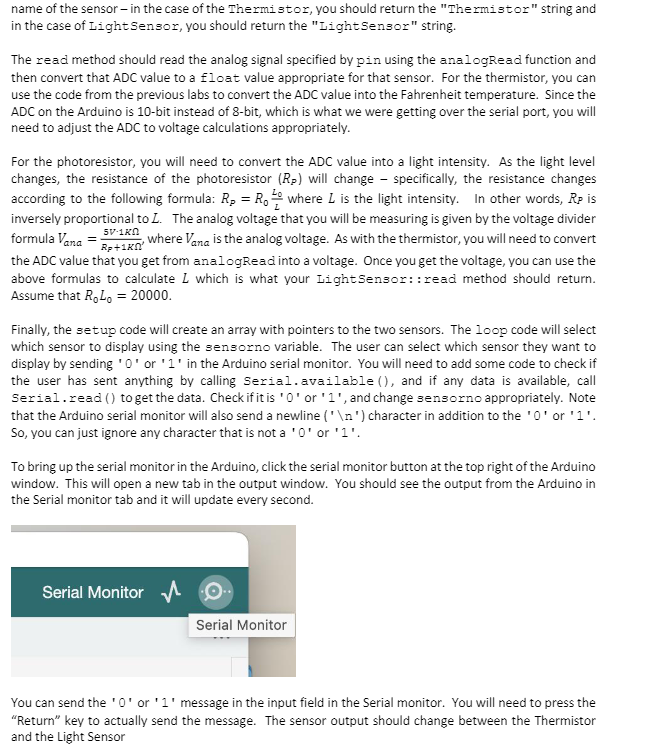
To bring up the serial monitor in the Arduino, click the serial monitor button at the top right of the Arduino
window. This will open a new tab in the output window. You should see the output from the Arduino in
the Serial monitor tab and it will update every second.
Serial Monitor
Serial Monitor
You can send the '0' or '1' message in the input field in the Serial monitor. You will need to press the
"Return" key to actually send the message. The sensor output should change between the Thermistor
and the Light Sensor
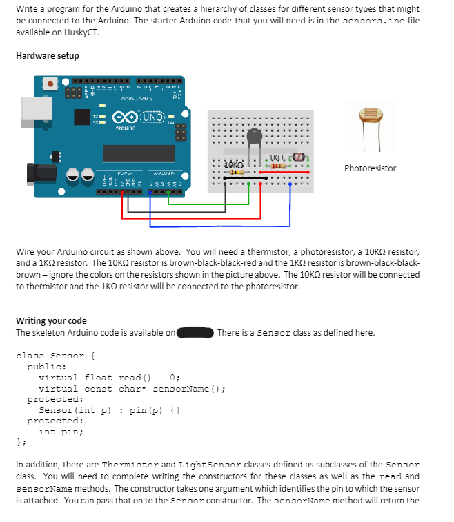
Transcribed Image Text:Write a program for the Arduino that creates a hierarchy of classes for different sensor types that might
be connected to the Arduino. The starter Arduino code that you will need is in the sensors.ino file
available on HuskyCT.
Hardware setup
NATA PVM-)
O UNO
Arduino
ANALUSIN
252234
888
• ΙΚΩ,
Photoresistor
Wire your Arduino circuit as shown above. You will need a thermistor, a photoresistor, a 10K resistor,
and a 1KQ resistor. The 10K resistor is brown-black-black-red and the 1KQ resistor is brown-black-black-
brown-ignore the colors on the resistors shown in the picture above. The 10K resistor will be connected
to thermistor and the 1KQ resistor will be connected to the photoresistor.
Writing your code
The skeleton Arduino code is available on
class Sensor {
};
public:
virtual float read() = 0;
There is a Sensor class as defined here.
virtual const char* sensorName();
protected:
Sensor (int p)
protected:
int pin;
pin (p) {})
In addition, there are Thermistor and Light Sensor classes defined as subclasses of the Sensor
class. You will need to complete writing the constructors for these classes as well as the read and
sensorName methods. The constructor takes one argument which identifies the pin to which the sensor
is attached. You can pass that on to the Sensor constructor. The sensorName method will return the
Expert Solution
This question has been solved!
Explore an expertly crafted, step-by-step solution for a thorough understanding of key concepts.

This is a popular solution!

Trending now
This is a popular solution!

Step by step
Solved in 2 steps

Recommended textbooks for you
EBK JAVA PROGRAMMING
Computer Science
ISBN:
9781337671385
Author:
FARRELL
Publisher:
CENGAGE LEARNING - CONSIGNMENT
EBK JAVA PROGRAMMING
Computer Science
ISBN:
9781337671385
Author:
FARRELL
Publisher:
CENGAGE LEARNING - CONSIGNMENT