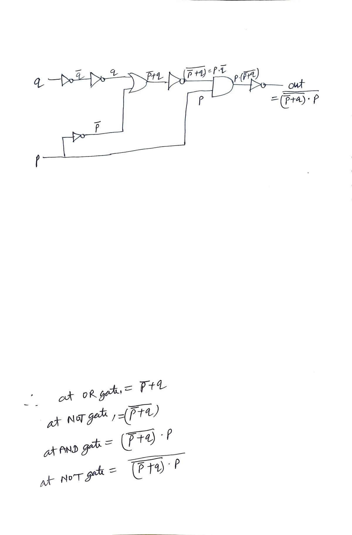
Write the logic expression that represents the output of the following circuit as a function of its inputs. (Do not simplify your expression). - OUT Use logic rules to simplify your expression. Show each step and state the law of logical equivalence that are appling at each step


Q: 2) For the circuit shown below (please answer a and b): (a) Write the Boolean functions for the four…
A: Each of the AND gates is accepting 3 inputs. Each of the OR gates is accepting 2 inputs. We have…
Q: Despite this, I am still not quite certain that I get the concept of "two level logic." Is there any…
A: Introduction: A logic architecture with no more than two logic gates between the input and output is…
Q: write a program to print the truth table of the following logic circuit: C++ D-
A: Given:
Q: Transform the following Boolean expression into a Logic Diagram and convert into NOR gate…
A:
Q: A B F From the above logic circuit, F value is o when a. All options are correct O b. A=0, B=0, C=1…
A: Answer is : All options are correct
Q: b) For the following circuits, find a Boolean expression and construct the truth table A B
A:
Q: Q1: Draw the circuit for this Boolean expression after simplification ,then Find the truth table…
A: The answer is in below steps:
Q: Write the Boolean expression for the logic diagram given below and simplify it as much as possible…
A: Requirements :-
Q: (a) Draw a logic circuit for the case where the output, ENABLE, is HIGH only if the inputs, ASSERT…
A: Given: a) Draw a logic circuit for the case where the output, ENABLE, is HIGH only if the inputs,…
Q: Write the Boolean Expression for the output of the following logic systems.
A:
Q: Draw the logic diagram corresponding to the following Boolean expression without simplifying it: F =…
A: The logic diagram for the given expression can be drawn using the following symbols: AND The AND…
Q: Q2. Simplify the following Boolean expression to a minimum number of literals and draw the logic…
A: Part(a) Following is the simplification of the boolean expression: Given boolean expression:(x' +…
Q: Create a Boolean expression for the logic circuit shown in the diagram below?
A: In the given logical circuit, four gates are used. OR gate, AND gate, NOT gate, and a NOR gate.…
Q: Fill in the blanks to prove that the circuits have the same input/output table by showing that the…
A: Actually, given question regarding Boolean expressions ...
Q: Write the Boolean Expression for the output of the following logic systems. Bo
A: A Boolean expression is an logical expression or statement that could be either true or false. These…
Q: What Boolean function does the following circuit represent? A Y
A: Given The circuit
Q: Write the Boolean Expression for the output of the following logic systems. B Do
A:
Q: Draw logic diagrams of the circuits that implement the original and simplified expressions…
A:
Q: Activity Draw the logic circuits and complete the truth tables for the following logic statements.…
A: Here in this question we have given a condition for some output variable R to be 1. We have asked to…
Q: A BO
A: The above question is solved in step 2:-
Q: F = (A+ B) (A+B)
A: Find Your Answer Below
Q: Consider the Boolean expression F3 (x'у).(х + х.у). a) Draw the logic diagram corresponding to the…
A:
Q: Create a non-abbreviated logic diagram for the following Boolean Expressions. You can use all gates.…
A: To create the non abbreviated logic diagram of Boolean expression a’b+ab’ first of all , you need…
Q: The logic circuit below is supposed to be designed to produce the truth table also shown below.…
A:
Q: Create a Boolean expression for the logic circuit shown in the diagram below? х
A: This given figure creates the following Boolean expression: F=x~y+~ ((x+y).z) Explanation of logic…
Q: Create a non-abbreviated logic diagram for the following Boolean Expressions. You can use all gates.…
A: Logic diagram of expression (a XOR b + b’ XOR c’) is given below,
Q: Examine the Boolean expression by using the state assignment table and also discuss briefly how the…
A: Answer: I have given answer in the handwritten format.
Q: Write a logic statement that corresponds with the given logic circuits:
A: Given logic circuit contains three input variables A, B and C and one output variables X. This…
Q: Given the following circuit, answer the followed questions. A B C a. Obtain the Boolean expression…
A:
Q: A. F = xy +x y B. F, = xyz + x y + xy z C. F, = xyw+ x(wz + wz) D. F, = (A+ B) (A+ B) %3D
A: - With the restrictions placed on us because of our guidelines we are allowed to answer the first…
Q: -Y B -
A:
Q: 2- Write the Boolean equations and draw the logic diagram of the circuit whose outputs are defined…
A:
Q: 4-Draw the logic circuit represented the following truth table. INPUT A INPUT B INPUT C OUTPUT P 1 1…
A: Solution 4 For the high output P(value 1), P=A¯ B¯ C¯ + A¯ B¯ C Disclaimer: Since you have…
Q: Draw the logic diagram of the following Boolean expression after simplifying it: A+CD+(A+D')(C'+D)
A: Ans:) The solved expression and the logic diagram is given below.
Q: b) Prove: (A + B)(A + C) = A + B.C c) Draw the logic diagram after simplifying the above expression…
A: Q: Prove given logical expression and draw the logic diagram
Q: . Draw a circuit diagram using appropriate logic gates to implement a 3-bit comparator. Identify the…
A:
Q: Use Boolean algebra to simplify the following expression, then draw a logic diagram and truth table…
A: Here Simplified expression is given, we have to draw the logic diagram for that and also create…
Q: Draw a logic circuit diagram of the below expression. AB'+ BC' it would be great help..if you…
A: The logic circuit diagram for the given expression is shown below - Explanation - There are…
Q: 4-Draw the logic circuit represented 5-Draw the logic circuit represented the following truth table.…
A: NOTE: According to the guidelines only the first question is answered. 4. Truth Table: INPUT A…
Q: Connect the following Boolean expression using the fewest possible number of logic gates (AND, OR,…
A: Step 1:- F=A'B'C+A'BC'+ABC'+ABC Solve this expression by the k-map. 3-variable k-map is:-
Q: Are the following two logic circuits equivalent and write the final equation for the circuits:- * B…
A: a) AB + CD
Q: 2- Write the Boolean equations and draw the logic diagram of the circuit whose outputs are defined…
A:
Q: Use the truth table below, to find the Boolean expression and draw the logic circuit diagram using…
A: Here in this question we have given a k-map with four variable A B C D. And we have asked to use…
Q: 1. Simplify the follow expression algebraically: F3D A. B.С + A.B.С + А. В.С + A. В.С 2. Write the…
A:
Q: Q2/ Realize the truth table and straight connection for the following statements NOTE: USE LOGISIM…
A: A truth table shows how the truth or falsity of a compound statement depends on the truth or falsity…
Q: Convert the truth table below to a Boolean equation, and then simplify it and develop logic network.…
A: To get the SOP form of boolean equation from truth table find the minterm from truth table whose…
Q: Write down the functions of the logic circuits given below and simplify them?
A: Function- Y = (ABC + A') . (C' + A) Simplification - Y = (ABC + A') . (C' + A) = (ABC + A')C' +…
Q: A law that states that when inputs to a logic symbol are ANDed and Ored, the order in which they are…
A: According to Commutative law, A+B = B+A and A.B=B.A So no matter in which order we take inputs,…
Q: From the given choices find the Boolean expression of the Logic circuit: ABC
A: first gate is AND gate so f1=AB'C (because B contain NOT gate) second gate is also AND gate so…


Trending now
This is a popular solution!

Step by step
Solved in 3 steps with 3 images


- We consider a circuit having four inputs and one output. The output has the value 1 if at least half of the inputs have the value 1. In this case, the circuit is a not-a-minority circuit. 1) Build a truth table for the circuit presented in the description above. 2) Using this truth table, find a Boolean expression which represents the same function, and by using Boolean algebra, simplify it as much as possible. 3) Verify the design of the circuit.5. Consider the circuit below: A- B- C- a. Write the Boolean expression modeled by the circuit. Above. Use Boolean Algebra notation: A, (for not A); AB (for A and B), A + B (for A or B), A Ð B (A xor B), etc. b. Evaluate the output of each gate, including the final gate, given that A= 1, B=1 and C=1 Write your evaluation of each gate above each gate and include a screen shot1. Use the 2-input version of the basic AND, OR, NOT gates to implement the following Boolean expression. Insert a drawing of your circuit here. Expression: (A + B)č. Use the 2-input version of the basic AND, OR, NOT gates to implement the following Boolean expression. Insert a drawing of your circuit here. Expression: (AB)(BC). Write the Boolean expression that is equivalent to the following circuit. D 2. Use the Word table tool to construct the truth table for this circuit. Be sure to include intermediate values. Insert columradings in the first row. Be sure to use the Insert > Equation tool so that standard Boolean logic symbols are displayed in the headings.
- Draw logic diagram of the circuit that implement the original and simplified expression in part 4. This is included with part 4 above1. Use the 2-input version of the basic AND, OR, NOT gates to implement the following Boolean expression. Insert a drawing of your circuit here. Expression: (A + B)T Use the 2-input version of the basic AND, OR, NOT gates to implement the following Boolean expression. Insert a drawing of your circuit here. Expression: (AB)(BC) Write the Boolean expression that is equivalent to the following circuit. B. D.Design a circuit to implement the following truth table, where A and B are inputs and Z is the output. Give the Boolean equation that implements the circuit in the space provided. There may be more than one possible correct answer. You only need to list one possible correct answer. Input Output A B Z 0 0 1 0 1 0 1 0 1 1 1 1
- 6. For the following Verilog code, draw the corresponding circuit diagram for "bigMod". Your circuit should only involve standard gates (AND, OR, NAND, NOR, XOR, Inverter), and the variable names Val, X, Y, and Z. DO NOT SIMPLIFY THE CIRCUIT. Note: all of the code is legal Verilog, with no errors. module tstMod (F, A, B, C); output logic F; input logic A, B, C; assign F endmodule = (A & ~B & C) | (A & C) | ~B; module bigMod (Val, X, Y, output logic Val; input logic X, Y, Z; logic T; Z); .C (Y)); tstMod T1 (.F (T), .A (X), .B (1'bl), tstMod T2 (.F (Val), .A(Z), .B (T), .C (X)); endmodule9. Construct a truth table summarizing the operation of this circuit: A B C Out 10. Write a boolean expression for the circuit shown above. (Note: Do not simplify it.) 11. Write the simplified boolean expression for the circuit based on the truth table. 12. Picnics are enjoyable on sunny days that have no ants. They're also enjoyable anytime there's a hummingbird, as well as on days where there are ants and ladybugs. Write a Boolean equation for picnic enjoyment (E) in terms of sun (S), ants (A), hummingbirds (H), and ladybugs (L).implement the following circuit. Write the boolean expression describing its outputs
- Task 4: Simplifying Boolean functions Simplify the following Boolean expression F (A, B, C) = (A+C") +C (C.A' + (B.A) +C Draw the simplified Boolean expression using EWB. Find out the truth table of the circuit.Q1. A logic circuit implements the following Boolean function: F= A'C + AC'D' It is found that the circuit input combination A = C = 0 can never occur. Find a simpler expression for F using the proper don't care conditions. Design the logic circuit using the expression you find.F = ((NOT P AND NOT Q) AND R) OR (Q AND R) a) Draw a logic circuit for the above Boolean expression b) write a truth table