
University Physics (14th Edition)
14th Edition
ISBN: 9780133969290
Author: Hugh D. Young, Roger A. Freedman
Publisher: PEARSON
expand_more
expand_more
format_list_bulleted
Videos
Textbook Question
Chapter 26, Problem 26.33E
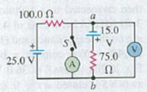
In the circuit shown in Fig. E26.33 all meters are idealized and the batteries have no appreciable internal resistance, (a) Find the reading of the voltmeter with the switch S open. Which point is at a higher potential: a or b? (b) With S closed, find the reading of the voltmeter and the ammeter. Which way (up or down) does the current flow through the switch?
Figure E26.33
Expert Solution & Answer
Want to see the full answer?
Check out a sample textbook solution
Students have asked these similar questions
25.54. In the circuit shown in
Fig. P25.54, R is a variable resistor whose
value ranges from 0 to co, and a and b are
the terminals of a battery that has an emf
E = 15.0V and an internal resistance of
4.00 2. The ammeter and voltmeter are
idealized meters. As R varies over its full
range of values, what will be the largest
and smallest readings of (a) the voltmeter
and (b) the ammeter? (c) Sketch qualita-
tive graphs of the readings of both meters
as functions of R.
Figure P25.54
R
A capacitor charging circuit consists of a battery, an uncharged 20 μF capacitor, and a 5.6 kΩkΩ resistor. At t = 0 ss the switch is closed; 0.15 s later, the current is 0.46 mA . What is the battery's emf?
Figure E26.26
2.00 210.00 V
a
ww
1.00 2 5.00 V
www
10.00 Ω
ww
26.27 The 10.00 V battery in Fig. E26.26 is removed from the cir-
cuit and reinserted with the opposite polarity, so that its positive ter-
minal is now next to point a. The rest of the circuit is as shown in the
figure. Find (a) the current in each branch and (b) the potential differ-
ence Van of point a relative to point b.
3.00 Ω
4.00 Ω
b
Chapter 26 Solutions
University Physics (14th Edition)
Ch. 26 - In which 120-V light bulb does the filament have...Ch. 26 - Two 120-V light bulbs, one 25-W and one 200-W,...Ch. 26 - You connect a number of identical light bulbs to a...Ch. 26 - In the circuit shown in Fig. Q26.4, three...Ch. 26 - If two resistors R1 and R2 (R2 R1) are connected...Ch. 26 - If two resistors R1 and R2 (R2 R1) are connected...Ch. 26 - A battery with no internal resistance is connected...Ch. 26 - A resistor consists of three identical metal...Ch. 26 - A light bulb is connected in the circuit shown in...Ch. 26 - A real battery, having nonnegligible internal...
Ch. 26 - If the battery in Discussion Question Q26.10 is...Ch. 26 - Consider the circuit shown in Fig. Q26.12. What...Ch. 26 - Is it possible to connect resistors together in a...Ch. 26 - The battery in the circuit shown in Fig. Q26.14...Ch. 26 - In a two-cell flashlight, the batteries are...Ch. 26 - Identical light bulbs A, B, and C are connected as...Ch. 26 - The emf of a flashlight battery is roughly...Ch. 26 - Will the capacitors in the circuits shown in Fig....Ch. 26 - Verify that the time constant RC has units of...Ch. 26 - For very large resistances it is easy to construct...Ch. 26 - When a capacitor, battery, and resistor are...Ch. 26 - A uniform wire of resistance R is cut into three...Ch. 26 - A machine part has a resistor X protruding from an...Ch. 26 - A resistor with R1 = 25.0 is connected to a...Ch. 26 - A 42- resistor and a 20- resistor are connected in...Ch. 26 - A triangular array of resistors is shown in Fig....Ch. 26 - For the circuit shown in Fig. E26.6 both meters...Ch. 26 - For the circuit shown in Fig. E26.7 find the...Ch. 26 - Three resistors having resistances of 1.60 , 2.40...Ch. 26 - Now the three resistors of Exercise 26.8 are...Ch. 26 - Power Rating of a Resistor. The power rating of a...Ch. 26 - In Fig. E26.11, R1, = 3.00 , R2 = 6.00 , and R3=...Ch. 26 - In Fig. E26.11 the battery has emf 35.0 V and...Ch. 26 - Compute the equivalent resistance of the network...Ch. 26 - Compute the equivalent resistance of the network...Ch. 26 - In the circuit of Fig. E26.15, each resistor...Ch. 26 - Consider the circuit shown in Fig. E26.16. The...Ch. 26 - In the circuit shown in Fig. E26.17, the voltage...Ch. 26 - In the circuit shown in Fig. E26.18, = 36.0 V,...Ch. 26 - CP In the circuit in Fig. E26.19, a 20.0- resistor...Ch. 26 - In the circuit shown in Fig. E26.20, the rate at...Ch. 26 - Light Bulbs in Series and in Parallel. Two light...Ch. 26 - Light Bulbs in Series. A 60-W, 120-V light bulb...Ch. 26 - In the circuit shown in Fig. E26.23, ammeter A1...Ch. 26 - The batteries shown in the circuit in Fig. E26.24...Ch. 26 - In the circuit shown in Fig. E26.25 find (a) the...Ch. 26 - Find the emfs 1 and 2 in the circuit of Fig....Ch. 26 - In the circuit shown in Fig. E26.27, find (a) the...Ch. 26 - In the circuit shown in Fig. E26.28, find (a) the...Ch. 26 - The 10.00-V battery in Fig. E26.28 is removed from...Ch. 26 - The 5.00-V battery in Fig. E26.28 is removed from...Ch. 26 - In the circuit shown in Fig. E26.31 the batteries...Ch. 26 - In the circuit shown in Fig. E26.32 both batteries...Ch. 26 - In the circuit shown in Fig. E26.33 all meters are...Ch. 26 - In the circuit shown in Fig. E26.34, the 6.0-...Ch. 26 - The resistance of a galvanometer coil is 25.0 ,...Ch. 26 - The resistance of the coil of a pivoted coil...Ch. 26 - A circuit consists of a series combination of...Ch. 26 - A galvanometer having a resistance of 25.0 has a...Ch. 26 - A capacitor is charged to a potential of 12.0 V...Ch. 26 - You connect a battery, resistor, and capacitor as...Ch. 26 - A 4.60-F capacitor that is initially uncharged is...Ch. 26 - You connect a battery, resistor, and capacitor as...Ch. 26 - CP In the circuit shown in Fig. E26.43 both...Ch. 26 - A 12.4-F capacitor is connected through a 0.895-M...Ch. 26 - An emf source with = 120 V, a resistor with R =...Ch. 26 - A resistor and a capacitor are connected in series...Ch. 26 - CP In the circuit shown in Fig. E26.47 each...Ch. 26 - A 1.50-F capacitor is charging through a 12.0-...Ch. 26 - In the circuit in Fig. E26.49 the capacitors are...Ch. 26 - A 12.0-F capacitor is charged to a potential of...Ch. 26 - In the circuit shown in Fig. E26.51, C = 5.90 F, ...Ch. 26 - Prob. 26.52ECh. 26 - A 1500-W electric beater is plugged into the...Ch. 26 - In Fig. P26.54, the battery has negligible...Ch. 26 - The two identical light bulbs in Example 26.2...Ch. 26 - Each of the three resistors in Fig. P26.56 has a...Ch. 26 - (a) Find the potential of point a with respect to...Ch. 26 - CP For the circuit shown in Fig. P26.58 a 20.0-...Ch. 26 - Calculate the three currents I1, I2, and I3...Ch. 26 - What must the emf in Fig. P26.60 be in order for...Ch. 26 - Find the current through each of the three...Ch. 26 - (a) Find the current through the battery and each...Ch. 26 - Consider the circuit shown in Fig. P26.63. (a)...Ch. 26 - In the circuit shown in Fig. P26.64, = 24.0 V,...Ch. 26 - In the circuit shown in Fig. P26.65, the current...Ch. 26 - In the circuit shown in Fig. P26.66 all the...Ch. 26 - Figure P26.67 employs a convention often used in...Ch. 26 - Three identical resistors are connected in series....Ch. 26 - A resistor R1 consumes electrical power P1 when...Ch. 26 - The capacitor in Fig. F26.70 is initially...Ch. 26 - A 2.00-F capacitor that is initially uncharged is...Ch. 26 - A 6.00-F capacitor that is initially uncharged is...Ch. 26 - Point a in Fig. P26.73 is maintained at a constant...Ch. 26 - The Wheatstone Bridge. The circuit shown in Fig....Ch. 26 - (See Problem 26.67.) (a) What is the potential of...Ch. 26 - A 2.36-F capacitor that is initially uncharged is...Ch. 26 - A 224- resistor and a 589- resistor are connected...Ch. 26 - A resistor with R = 850 is connected to the...Ch. 26 - A capacitor that is initially uncharged is...Ch. 26 - DATA You set up the circuit shown in Fig. 26.22a,...Ch. 26 - DATA You set up the circuit shown in Fig. 26.20....Ch. 26 - DATA The electronics supply company where you work...Ch. 26 - An Infinite Network. As shown in Fig. P26.83, a...Ch. 26 - Suppose a resistor R lies along each edge of a...Ch. 26 - BIO Attenuator Chains and Axons. The infinite...Ch. 26 - Assume that a typical open ion channel spanning an...Ch. 26 - In a simple model of an axon conducting a nerve...Ch. 26 - Cell membranes across a wide variety of organisms...
Additional Science Textbook Solutions
Find more solutions based on key concepts
Show that the acceleration of any object down an incline where friction behaves simply (that is, where fk=kN ) ...
College Physics
76. The radioactive element radium (Ra) decays by a process known as alpha decay, in which the nucleus emits a ...
College Physics: A Strategic Approach (4th Edition)
49. A gray kangaroo can bound across level ground with each jump carrying it 10 m from the takeoff point. Typic...
Physics for Scientists and Engineers: A Strategic Approach, Vol. 1 (Chs 1-21) (4th Edition)
3. What is free-fall, and why does it make you weightless? Briefly describe why astronauts are weightless in th...
The Cosmic Perspective (8th Edition)
In this activity, we will use a representation of the atom in which a central nucleus containing the protons an...
Lecture- Tutorials for Introductory Astronomy
1. When is energy most evident?
Conceptual Physics (12th Edition)
Knowledge Booster


Learn more about
Need a deep-dive on the concept behind this application? Look no further. Learn more about this topic, physics and related others by exploring similar questions and additional content below.Similar questions
- The values of the components in a simple series RC circuit containing a switch (Fig. P21.53) are C = 1.00 F, R = 2.00 106 , and = 10.0 V. At the instant 10.0 s after the switch is closed, calculate (a) the charge on the capacitor, (b) the current in the resistor, (c) the rate at which energy is being stored in the capacitor, and (d) the rate at which energy is being delivered by the battery.arrow_forwardA capacitor charging circuit consists of a battery, an uncharged 20 μF capacitor, and a 4.0 kΩ resistor. At t = 0 s, the switch is closed; 0.15 s later, the current is 0.46 mA. What is the battery’s emf?arrow_forwardA solar cell generates a potential difference of 0.17 V when a 550 resistor is connected across it, and a potential difference of 0.24 V when a 970 resistor is substituted. What are the (a) internal resistance and (b) emf of the solar cell? (c) The area of the cell is 1.2 cm² and the rate per unit area at which it receives energy from light is 4.9 mW/cm². What is the efficiency of the cell for converting light energy to thermal energy in the 970 2 external resistor? (a) Number (b) Number (c) Number i Units Units Units Ω V perarrow_forward
- In the circuit shown both capacitors are initially charged to 45.0 V. (a) How long after closing the switch S will the potential across each capacitor be reduced to 10.0 V, and (b) what will be the current at that time? 15.0 20.0 50.0 N µF µF 30.0 Narrow_forwardsv 26.31 In the circuit shown in Fig. E26.31 all meters are idealized and the batteries have no appreciable internal resistance. (a) Find the read- ing of the voltmeter with the switch S open. Which point is at a higher poten- tial: a or b? (b) With S closed, find the reading of the voltmeter and the amme- 25.0 V 75.0 Ω ter. Which way (up or down) does the current flow through the switch? Figure E26.31 100.0 Ω a L15.0arrow_forwardA real battery consists of an emf, ?= 9.00V and has an internal resistance, r = 1.50Ω. The battery is connected in series with an ammeter, a load resistor of R = 3.00Ω, and an open switch. Determine the potential difference measured by the voltmeter.arrow_forward
- 26.29. In the circuit shown in Fig. E26.29 the batteries have neg- ligible internal resistance and the meters are both idealized. With the switch S open, the voltmeter reads 17.0 V. (a) Find the emf & of the bat- tery. (b) What will the ammeter read when the switch is closed? Figure E26.29 30.0 Ω www 20.0 75.0 52 25.0 V 50.0 Ω Ω ε = ? $1arrow_forwardThe figure below shows a capacitor, with capacitance C = 8.22 UF, and a resistor, with resistance R = 5.98 MN, connected in series to a battery, with E = 29.0 V. The circuit has a switch, which is initially open. R (a) What is the circuit's time constant (in seconds)? (b) What is the maximum charge (in µC) on the capacitor after the switch is closed? (c) What is the current (in pA) through the resistor 10.0 s after the switch is closed? HAarrow_forwardE2 R1 R2 2. Find the charge on the capacitor after the switch has been left open for some time, then closed for some period of time. We can assume that C = 2 µF, with batteries of values E1 = 2V and E2 = 1 V, and resistor values R1 R2 = 0.25 2. 0.52 andarrow_forward
- 26.23. In the circuit shown in Fig. E26.23 find (a) the current in re- sistor R; (b) the resistance R; (c) the unknown emf E. (d) If the circuit is broken at point x, what is the current in resistor R? Figure E26.23 28.0 V R E 4.00 A - ww x 6.00 Ω 6.00 A 3.00 Ω 26.25 In the circuit shown in Fig. E26.25, find (a) the current in the 3.00 resistor; (b) the unknown emfs &₁ and E2; (c) the resistance R. Note that three currents are given. Figure E26.25 2,00 A R www 6.00 Ω 15.00 A 4.00 ΩΣ 3.00 A • 3.00 Ωarrow_forwardA series circuit is comprised of a 200VDC battery, a switch, a 1 kΩ resistor and a 10000 µF capacitor. Initially the switch is open and the capacitor is uncharged. What is the resistor voltage 29 seconds after the switch is closed? answer should be in V.arrow_forwardTwo 3.0 μF capacitors are in series with a resistor of 150 Ω, a battery of15.0 V, and an open switch. What is the time constant of the circuit? Whatis the equation for the current as a function of time?arrow_forward
arrow_back_ios
SEE MORE QUESTIONS
arrow_forward_ios
Recommended textbooks for you
 Physics for Scientists and Engineers: Foundations...PhysicsISBN:9781133939146Author:Katz, Debora M.Publisher:Cengage Learning
 Principles of Physics: A Calculus-Based TextPhysicsISBN:9781133104261Author:Raymond A. Serway, John W. JewettPublisher:Cengage Learning
Physics for Scientists and Engineers: Foundations...
Physics
ISBN:9781133939146
Author:Katz, Debora M.
Publisher:Cengage Learning
Principles of Physics: A Calculus-Based Text
Physics
ISBN:9781133104261
Author:Raymond A. Serway, John W. Jewett
Publisher:Cengage Learning
DC Series circuits explained - The basics working principle; Author: The Engineering Mindset;https://www.youtube.com/watch?v=VV6tZ3Aqfuc;License: Standard YouTube License, CC-BY