
Applied Statics and Strength of Materials (6th Edition)
6th Edition
ISBN: 9780133840544
Author: George F. Limbrunner, Craig D'Allaird, Leonard Spiegel
Publisher: PEARSON
expand_more
expand_more
format_list_bulleted
Concept explainers
Videos
Textbook Question
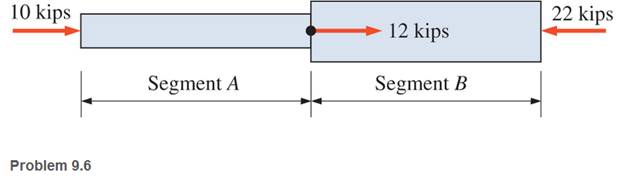
Chapter 9, Problem 9.6P
Determine the stresses in the two segments of the bar shown. Segment A has a diameter of
Expert Solution & Answer

Learn your wayIncludes step-by-step video

schedule03:58
Students have asked these similar questions
Q2: Find the shear load on bolt A for the
connection shown in Figure 2.
Dimensions are in mm
Fig. 2
24
0-0
0-0
A
180kN
(10 Mark
determine the direction and magnitude of angular velocity ω3 of link CD in the four-bar linkage using the relative velocity graphical method
Four-bar linkage mechanism, AB=40mm, BC=60mm, CD=70mm, AD=80mm, =60°, w1=10rad/s. Determine the direction and
magnitude of w3 using relative motion graphical method.
A
B
2
3
77777
477777
Chapter 9 Solutions
Applied Statics and Strength of Materials (6th Edition)
Ch. 9 - Write the direct stress formula in its three forms...Ch. 9 - A 6-in-diameter concrete test cylinder is loaded...Ch. 9 - Determine the tensile stress in each segment of...Ch. 9 - Calculate the stress developed in the following...Ch. 9 - The following members are subjected to axial...Ch. 9 - Determine the stresses in the two segments of the...Ch. 9 - A bin weighing 8 tons is supported by three steel...Ch. 9 - Diameters of small commercially available steel...Ch. 9 - A No. 32 (metric designation) reinforcing bar for...Ch. 9 - In the bolted connection of Figure 9.12 , assume...
Ch. 9 - Compute the force required to punch a...Ch. 9 - The 34 — in. — diameter bolt shown is subjected to...Ch. 9 - Why is strain unitless (or dimensionless)?Ch. 9 - (a) Given =1.2in. and L=100ft calculate (b) Given...Ch. 9 - A short compression member 2 in. by 2 in. in cross...Ch. 9 - A 100-ft-long rod is suspended from one end. The...Ch. 9 - Compute the total elongation of a steel bar,...Ch. 9 - A steel rod 34 in. in diameter and 25 ft long is...Ch. 9 - An aluminum rod 25mm in diameter and 4m long is...Ch. 9 - A steel rod 10 ft long is made up of two 5 ft...Ch. 9 - A titanium alloy bar elongates 0.500 in. when...Ch. 9 - Write a program that will calculate the allowable...Ch. 9 - Write a program that will compute stress, strain,...Ch. 9 - The Viking Bin Company manufactures suspended bins...Ch. 9 - Write a computer program that will calculate the...Ch. 9 - The joint between a diagonal and a chord in a...Ch. 9 - In Problem 9.26, find the required length of the...Ch. 9 - A column is supported by a base plate, pedestal,...Ch. 9 - If the soil pressure under the footing of Problem...Ch. 9 - A hopper weighing 75 kN is supported by three...Ch. 9 - A steel bar has a rectangular cross section 25 mm...Ch. 9 - A steel wire is suspended vertically from its...Ch. 9 - A W1240 shape is subjected to a tensile load of...Ch. 9 - Calculate the required diameter of steel tie rods...Ch. 9 - A 30-ft-long steel rod of circular cross section...Ch. 9 - Consider the bolted lap joint shown in Figure...Ch. 9 - An inclined member is braced with a glued block,...Ch. 9 - Calculate the force a punch press must exert if it...Ch. 9 - A 34 - in. - diameter punch is used to punch a...Ch. 9 - A control arm is keyed to a 1-in. -diameter shaft...Ch. 9 - Calculate the required width b for the key of...Ch. 9 - A 25-mm-diameter aluminum rod, 3 m long, is...Ch. 9 - A short timber post of Douglas fir is subjected to...Ch. 9 - A 1 00-ft surveyor’s steel tape with a...Ch. 9 - An 18-in-long steel rod is subjected to a tensile...Ch. 9 - Compute the magnitude of the tensile load that...Ch. 9 - A 5-mm-diameter steel wire, 18 m in length, is...Ch. 9 - A structural steel rod 112 in. in diameter and 20...Ch. 9 - A rectangular structural steel eyebar 34 in. thick...Ch. 9 - 9.50 A
in. — diameter steel rod, 100 ft long, is...Ch. 9 - For the truss shown, compute the total deformation...Ch. 9 - A steel bar with a cross section of 12 in. by 12...Ch. 9 - Rework Problem 9.52 , changing the second load...Ch. 9 - In the structure shown, the tie-back BC is a round...Ch. 9 - A hook is suspended by two steel wires, as shown....Ch. 9 - The trolley of a small hoist is supported on a...Ch. 9 - The steel piston rod to the master cylinder has a...Ch. 9 - A stranded steel brake cable is composed of 7...Ch. 9 - The piston of a steam engine is 400 mm in diameter...
Additional Engineering Textbook Solutions
Find more solutions based on key concepts
Porter’s competitive forces model: The model is used to provide a general view about the firms, the competitors...
Management Information Systems: Managing The Digital Firm (16th Edition)
Use the following tables for your answers to questions 3.7 through 3.51 : PET_OWNER (OwnerID, OwnerLasst Name, ...
Database Concepts (8th Edition)
If the rotation of the 100-mm-diameter A-36 steel shaft is = 800 rev/min., determine the absolute maximum shea...
Mechanics of Materials (10th Edition)
What is the disadvantage of having too many features in a language?
Concepts Of Programming Languages
What is an. abstract class?
Starting Out with Java: From Control Structures through Objects (7th Edition) (What's New in Computer Science)
This is a single piece of data within a record. a. field b. variable c. delimiter d. subrecord
Starting Out with Programming Logic and Design (5th Edition) (What's New in Computer Science)
Knowledge Booster


Learn more about
Need a deep-dive on the concept behind this application? Look no further. Learn more about this topic, mechanical-engineering and related others by exploring similar questions and additional content below.Similar questions
- Four-bar linkage mechanism, AB=40mm, BC=60mm, CD=70mm, AD=80mm, =60°, w1=10rad/s. Determine the direction and magnitude of w3 using relative motion graphical method. A B 2 3 77777 477777arrow_forwardThe evaporator of a vapor compression refrigeration cycle utilizing R-123 as the refrigerant isbeing used to chill water. The evaporator is a shell and tube heat exchanger with the water flowingthrough the tubes. The water enters the heat exchanger at a temperature of 54°F. The approachtemperature difference of the evaporator is 3°R. The evaporating pressure of the refrigeration cycleis 4.8 psia and the condensing pressure is 75 psia. The refrigerant is flowing through the cycle witha flow rate of 18,000 lbm/hr. The R-123 leaves the evaporator as a saturated vapor and leaves thecondenser as a saturated liquid. Determine the following:a. The outlet temperature of the chilled waterb. The volumetric flow rate of the chilled water (gpm)c. The UA product of the evaporator (Btu/h-°F)d. The heat transfer rate between the refrigerant and the water (tons)arrow_forward(Read image) (Answer given)arrow_forward
- Problem (17): water flowing in an open channel of a rectangular cross-section with width (b) transitions from a mild slope to a steep slope (i.e., from subcritical to supercritical flow) with normal water depths of (y₁) and (y2), respectively. Given the values of y₁ [m], y₂ [m], and b [m], calculate the discharge in the channel (Q) in [Lit/s]. Givens: y1 = 4.112 m y2 = 0.387 m b = 0.942 m Answers: ( 1 ) 1880.186 lit/s ( 2 ) 4042.945 lit/s ( 3 ) 2553.11 lit/s ( 4 ) 3130.448 lit/sarrow_forwardProblem (14): A pump is being used to lift water from an underground tank through a pipe of diameter (d) at discharge (Q). The total head loss until the pump entrance can be calculated as (h₁ = K[V²/2g]), h where (V) is the flow velocity in the pipe. The elevation difference between the pump and tank surface is (h). Given the values of h [cm], d [cm], and K [-], calculate the maximum discharge Q [Lit/s] beyond which cavitation would take place at the pump entrance. Assume Turbulent flow conditions. Givens: h = 120.31 cm d = 14.455 cm K = 8.976 Q Answers: (1) 94.917 lit/s (2) 49.048 lit/s ( 3 ) 80.722 lit/s 68.588 lit/s 4arrow_forwardProblem (13): A pump is being used to lift water from the bottom tank to the top tank in a galvanized iron pipe at a discharge (Q). The length and diameter of the pipe section from the bottom tank to the pump are (L₁) and (d₁), respectively. The length and diameter of the pipe section from the pump to the top tank are (L2) and (d2), respectively. Given the values of Q [L/s], L₁ [m], d₁ [m], L₂ [m], d₂ [m], calculate total head loss due to friction (i.e., major loss) in the pipe (hmajor-loss) in [cm]. Givens: L₁,d₁ Pump L₂,d2 오 0.533 lit/s L1 = 6920.729 m d1 = 1.065 m L2 = 70.946 m d2 0.072 m Answers: (1) 3.069 cm (2) 3.914 cm ( 3 ) 2.519 cm ( 4 ) 1.855 cm TABLE 8.1 Equivalent Roughness for New Pipes Pipe Riveted steel Concrete Wood stave Cast iron Galvanized iron Equivalent Roughness, & Feet Millimeters 0.003-0.03 0.9-9.0 0.001-0.01 0.3-3.0 0.0006-0.003 0.18-0.9 0.00085 0.26 0.0005 0.15 0.045 0.000005 0.0015 0.0 (smooth) 0.0 (smooth) Commercial steel or wrought iron 0.00015 Drawn…arrow_forward
- The flow rate is 12.275 Liters/s and the diameter is 6.266 cm.arrow_forwardAn experimental setup is being built to study the flow in a large water main (i.e., a large pipe). The water main is expected to convey a discharge (Qp). The experimental tube will be built at a length scale of 1/20 of the actual water main. After building the experimental setup, the pressure drop per unit length in the model tube (APm/Lm) is measured. Problem (20): Given the value of APm/Lm [kPa/m], and assuming pressure coefficient similitude, calculate the drop in the pressure per unit length of the water main (APP/Lp) in [Pa/m]. Givens: AP M/L m = 590.637 kPa/m meen Answers: ( 1 ) 59.369 Pa/m ( 2 ) 73.83 Pa/m (3) 95.443 Pa/m ( 4 ) 44.444 Pa/m *******arrow_forwardFind the reaction force in y if Ain = 0.169 m^2, Aout = 0.143 m^2, p_in = 0.552 atm, Q = 0.367 m^3/s, α = 31.72 degrees. The pipe is flat on the ground so do not factor in weight of the pipe and fluid.arrow_forward
- Find the reaction force in x if Ain = 0.301 m^2, Aout = 0.177 m^2, p_in = 1.338 atm, Q = 0.669 m^3/s, and α = 37.183 degreesarrow_forwardProblem 5: Three-Force Equilibrium A structural connection at point O is in equilibrium under the action of three forces. • • . Member A applies a force of 9 kN vertically upward along the y-axis. Member B applies an unknown force F at the angle shown. Member C applies an unknown force T along its length at an angle shown. Determine the magnitudes of forces F and T required for equilibrium, assuming 0 = 90° y 9 kN Aarrow_forwardProblem 19: Determine the force in members HG, HE, and DE of the truss, and state if the members are in tension or compression. 4 ft K J I H G B C D E F -3 ft -3 ft 3 ft 3 ft 3 ft- 1500 lb 1500 lb 1500 lb 1500 lb 1500 lbarrow_forward
arrow_back_ios
SEE MORE QUESTIONS
arrow_forward_ios
Recommended textbooks for you
 Elements Of ElectromagneticsMechanical EngineeringISBN:9780190698614Author:Sadiku, Matthew N. O.Publisher:Oxford University Press
 Mechanics of Materials (10th Edition)Mechanical EngineeringISBN:9780134319650Author:Russell C. HibbelerPublisher:PEARSON
 Thermodynamics: An Engineering ApproachMechanical EngineeringISBN:9781259822674Author:Yunus A. Cengel Dr., Michael A. BolesPublisher:McGraw-Hill Education
 Control Systems EngineeringMechanical EngineeringISBN:9781118170519Author:Norman S. NisePublisher:WILEY
 Mechanics of Materials (MindTap Course List)Mechanical EngineeringISBN:9781337093347Author:Barry J. Goodno, James M. GerePublisher:Cengage Learning
 Engineering Mechanics: StaticsMechanical EngineeringISBN:9781118807330Author:James L. Meriam, L. G. Kraige, J. N. BoltonPublisher:WILEY
Elements Of Electromagnetics
Mechanical Engineering
ISBN:9780190698614
Author:Sadiku, Matthew N. O.
Publisher:Oxford University Press
Mechanics of Materials (10th Edition)
Mechanical Engineering
ISBN:9780134319650
Author:Russell C. Hibbeler
Publisher:PEARSON
Thermodynamics: An Engineering Approach
Mechanical Engineering
ISBN:9781259822674
Author:Yunus A. Cengel Dr., Michael A. Boles
Publisher:McGraw-Hill Education
Control Systems Engineering
Mechanical Engineering
ISBN:9781118170519
Author:Norman S. Nise
Publisher:WILEY
Mechanics of Materials (MindTap Course List)
Mechanical Engineering
ISBN:9781337093347
Author:Barry J. Goodno, James M. Gere
Publisher:Cengage Learning
Engineering Mechanics: Statics
Mechanical Engineering
ISBN:9781118807330
Author:James L. Meriam, L. G. Kraige, J. N. Bolton
Publisher:WILEY
EVERYTHING on Axial Loading Normal Stress in 10 MINUTES - Mechanics of Materials; Author: Less Boring Lectures;https://www.youtube.com/watch?v=jQ-fNqZWrNg;License: Standard YouTube License, CC-BY