What is an AC Motor Drive?
An alternating current (AC) drive is an electronic device that transforms a set frequency and voltage to an adjustable frequency and adjustable voltage that can be supplied to motor compatible to it. It regulates the speed, torque, horsepower, and direction of an AC motor.
Classification of AC Drives
AC drives are used to power AC motors, particularly three-phase induction motors, which are more common than other motors in most sectors. Variable frequency drive (VFD), variable speed drive (VSD), or adjustable speed control drive (ASD) are all terms used to describe an AC drive.
Since there are various varieties of AC drives, they all operate on the same concept of transforming a fixed incoming voltage and frequency into a variable voltage and frequency output. The frequency of the drive dictates how fast the motor should operate, while the combination of voltage and frequency determines the amount of torque generated by the motor.
Power electronic converters, a central control unit (a microprocessor or microcontroller), filters, and various sensing devices all constitute a VFD.
Block Diagram of AC Drive Control
Construction
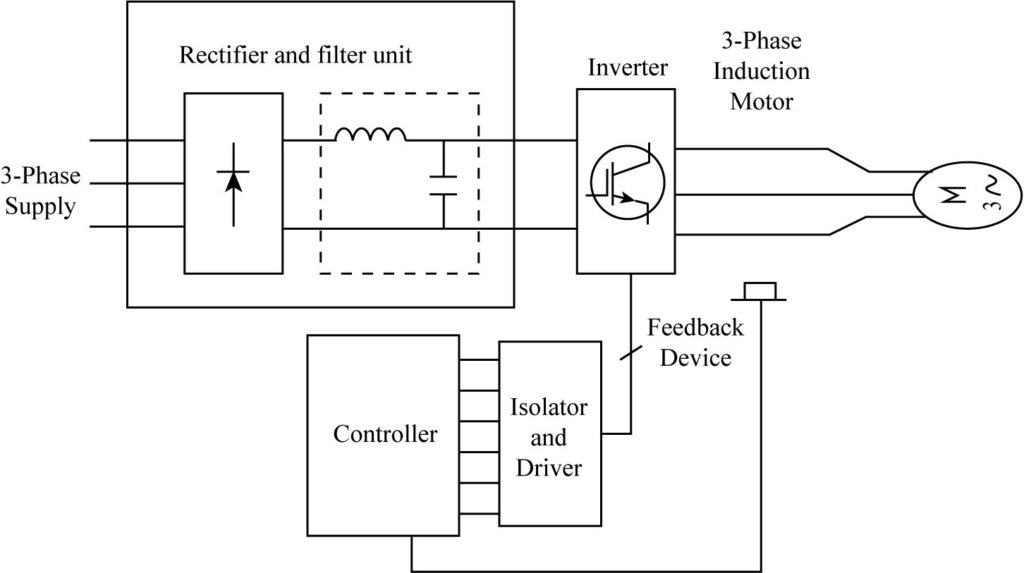
The figure 1 shows the schematic Block diagram of AC Drives. The block diagram consist of Rectifier and Filter circuit, Inverter circuit and Controller.
With minimal ripples, the Rectifier and Filter component turns AC power into DC power. The rectifier portion is often made up of diodes, which provide an uncontrolled DC output. After that, the filter section removes ripples and converts pulsating DC to fixed DC. The number of diodes in the rectifier is determined by the type of supply. For example, a three-phase supply necessitates a minimum of six diodes, that is why it is called a six-pulse converter.
Under the control of a microprocessor or microcontroller, the inverter receives DC power from the rectifier section and transforms it to AC power with variable voltage and frequency. This portion is made up of a sequence of transistors, IGBTs, SCRs, or MOSFETs, which are turned on and off by the controller's signals. The output and, eventually, the motor speed are determined by the turn-on of these power electronic components.
The controller is made up of a microprocessor or microcontroller that receives sensor input (as a speed reference) and user input (as a speed reference) and activates the power electronic components to adjust the frequency of the supply. Overvoltage and under voltage protection, power factor correction, temperature management, and PC connectivity for real-time monitoring are all included.
Working
The frequency of the supply (N = 120f/p) determines the speed of an induction motor, and we can achieve variable speed by changing the frequency. When the frequency is reduced, however, the torque increases, causing the motor to demand a large amount of current. As a result, the flux in the motor increases. If the supply voltage is not lowered, the magnetic field may also reach saturation levels.
In order to keep the flux within the operating range, both the voltage and frequency must be varied in a constant ratio. The torque remains constant throughout the operating range of v/f because it is proportional to the magnetic flux.
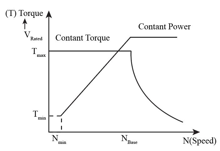
The torque and speed variation of an induction motor for voltage and frequency control are shown in the above diagram. Up until the base speed, voltage and frequency are varied at a constant ratio in the diagram. Up to the base speed, the flux and therefore torque are nearly constant. A constant torque region is what it is termed.
Because the supply voltage can only be modified up to the rated value, the base speed is the speed at the rated voltage. Beyond the base speed, increasing the frequency reduces the magnetic flux in the motor, resulting in torque loss. The term "flux weakening" or "constant power region" refers to this phenomenon. Constant v/f control method is the most common type of control in industries, and it is utilized in variable frequency drives (VFDs).
Control methods for VFD
For variable frequency drives, multiple speed controller approaches are used. The following is a list of the most common control strategies used in current VFDs.
- Scalar Control
- Vector Control
- Direct Torque Control
Scalar Control
Scalar control occurs when the magnitudes of voltage and frequency are modified while keeping the v/f ratio constant (scalar values determine the speed and torque). The motor is powered by variable voltage and frequency signals provided by an inverter's PWM control.
Depending on the manufacturer, the inverter can be controlled by a microcontroller, microprocessor, or any other digital controller. This control system is popular since it only requires a basic understanding of the motor to control the speed.
Vector Control
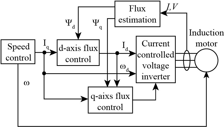
Indirect torque control, field oriented control, and flux oriented control are all terms used to describe this technology. The Clarke-Park transformation is used to convert three phase current vectors from a three-dimensional reference frame to a two-dimensional rotating reference frame (d-q). The flux producing component of the stator current is the 'd' component, and the torque producing component is the 'q' component.
Separate PI controllers control the two components, and the PI controller outputs are translated back to a three-dimensional static reference surface using the inversion of the Clarke-Park transformation.
The corresponding switching is pulse width modulated using the space vector modulation approach. Vector control approaches are classified into three types: stator flux oriented control, rotor flux oriented control, and magnetizing flux oriented control.
When compared to scalar control, vector control provides better torque response and more accurate speed control. However, it necessitates a sophisticated algorithm for speed computations and is more expensive than scalar control due to feedback devices.
Direct Torque Control
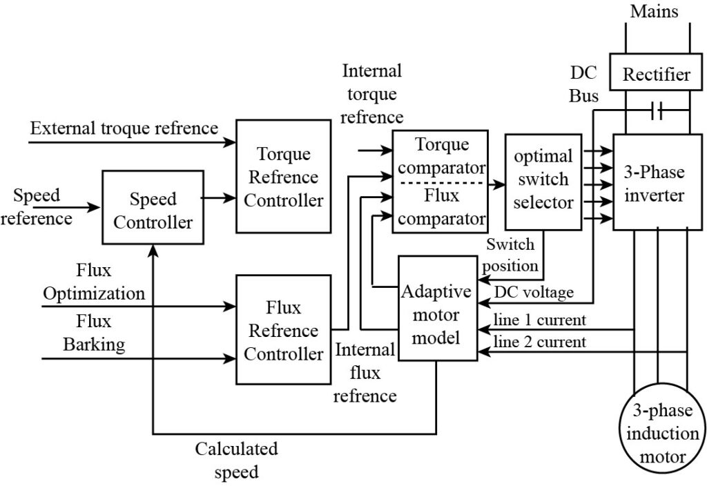
In contrast to typical vector control, this technique has no fixed switching pattern. It switches the inverter based on the load. Because there is no predefined switching pattern, this approach achieves a high reactivity, especially during load variations. It does not use any feedback, yet it ensures speed accuracy of up to 0.5 percent. This technique employs the adaptive motor model, which is based on basic motor theory mathematical expressions.
This model requires basic motor parameters such as stator resistance, saturation co-efficiency, mutual inductance, and so on, and the algorithm gathers this information without spinning the motor. This model computes the motor's actual torque and flux by taking into account inputs such as DC bus voltage, current switch position, and line currents. The torque and flux level comparators are then supplied these values.
The torque and flux reference signals are output from the comparators and fed into the switch selection table, where the selected switch position is applied to the inverter without any modulation. As a result, the motor torque and flux become directly controllable variables, hence the name direct torque control.
Advantages of AC Drive
- At lower speeds, there is a significant energy savings.
- Reduced working speed extends the life of rotating components.
- Noise and vibration levels have been reduced.
- Thermal and mechanical strains are reduced.
- KVA rating is lower.
Context and Applications
There are any applications of of AC mmotor drives, such as
- Application in devices like fans, blowers, compressors, pumps
- Application in mechanical shops in machine tools, grinders, lathes, stamping presses
- Industrial application like in conveyors, belts, chains, screws, bulk/packaged material handlers
- Manufacturing applications like in custom machines, labelers, bottle washers, wire drawing, textiles, etc.
In each of the expert exams for undergraduate and graduate publications, this topic is mainly used for
- Bachelor of technology in Electrical Engineering
- Master of technology in Electrical Engineering
- Bachelor of technology in Mechanical Engineering
- Master of technology in Mechanical Engineering
Related Concepts
- DC motor working on AC supply
- DC motor speed control
- Speed control of AC drive
- AC Motors
Common Mistakes
- Make sure motor is not overloaded.
- Make sure that protection devices must be of appropriate ratings.
- Make sure to keep a track of the insulation of the winding as it degrades owing to overheating, corrosion, or physical damage, resulting in low resistance.
- Make sure there are no vibration as it can occur as a result of a motor problem, such as loose bearings, misalignment, or corrosion.
- Wiring must be correctly done to avoid any kind of fault.
Practice Problems
Q1. An AC Drive is an electronic device that transform a set of .................... and .......... to an adjustable frequency and voltage source of alternating current (AC).
A. Frequency and Voltage
B. Current and Voltage
C. Frequency and current
D. None
Answer: A
Explanation: An AC Drive is an electronic device that transforms a set frequency and voltage to an adjustable frequency and voltage source of alternating current (AC).
Q2. What is the control method for VED?
A. Scalar Control
B. Vector Control
C. Direct Torque Control
D. All of the above
Answer: D
Explanation: Scalar control, vector control and direct torque control these all are types of VFD.
Q3. Scalar control occurs when the magnitudes of voltage and frequency are modified while keeping the ……………. ratio constant.
A.N/f
B. 120/f
C. V/f
D. None
Answer: C
Explanation: Scalar control occurs when the magnitudes of voltage and frequency are modified while keeping the v/f ratio constant.
Q4. Indirect torque control, flux oriented control, field oriented control, and flux oriented control are all terms used to describe ……………… method.
A. Scalar Control
B. Vector Control
C. Direct Torque Control
D. None.
Answer: B
Explanation: Indirect torque control, flux oriented control, field oriented control, and flux oriented control are all terms used to describe this technology.
Q5. …………………technique has no fixed switching pattern.
A. Scalar Control
B. Vector Control
C. Direct Torque Control
D. None.
Answer: C
Explanation: In contrast to typical vector control, this technique has no fixed switching pattern. It switches the inverter based on the load.
Want more help with your electrical engineering homework?
*Response times may vary by subject and question complexity. Median response time is 34 minutes for paid subscribers and may be longer for promotional offers.
Search. Solve. Succeed!
Study smarter access to millions of step-by step textbook solutions, our Q&A library, and AI powered Math Solver. Plus, you get 30 questions to ask an expert each month.
Search. Solve. Succeed!
Study smarter access to millions of step-by step textbook solutions, our Q&A library, and AI powered Math Solver. Plus, you get 30 questions to ask an expert each month.