What is a circuit?
Circuits can be classified as parallel and series depending on the manner in which components are connected to one another and the electrical source. The resultant output of the circuit depends on the electrical component.
If two components in a circuit share a single common node, the circuit is classified as a series circuit. If two components share two nodes, the circuit is in parallel connection. A combination of circuits can be created using both the series and parallel connections.
Components of a circuit
Basic components used in a circuit are:
Resistor
The electrical component that provides a restriction to the flow of current in a circuit is called a resistor. Resistance is a measure of resistance exerted by the resistor in a circuit. It is a passive component that reduces the flow of current in a circuit. It is mainly used to adjust the signal levels and to divide voltages in circuits.
The resistor has a marking code that helps the user to understand the value of resistance. Ohms law states the relationship between voltage and current. The proportionality constant between the voltage and current is resistance. The unit of resistance is Ohm ().
Capacitor
An electrical component that can store energy in the form of an electric field is known as a capacitor. Capacitance is the effect of a capacitor. It is a passive component with two terminals marked as positive and negative. It consists of two parallel plates separated by a vacuum or insulator. Opposite charges are accumulated in these plates and the electric field is stored in between.
Capacitance is the ratio of charge to voltage, and its unit is Farad. They exist in different physical forms and a few types of capacitors are ceramic capacitors, semiconductor capacitors, parallel plate capacitors, and electrical capacitors.
Inductor
An electrical component that stores energy in the form of a magnetic field is known as an inductor. It is a passive two-terminal component that resembles a coil of insulated wires.
It works on the relationship between change in current flow and magnetic field. A magnetic field is induced because of the changing current in the coil, and this is explained by the Faradays law of induction.
Inductance is the effect of an inductor and is defined as a ratio between voltage to the change in current. Its unit is Henry.
Inductors are mainly used to create electronic filters in radio and TV receivers.
Current source
An electrical component that delivers electrical current in a circuit independent of the voltage is known as a current source. Current stores are represented as two-terminal components that provide a constant current supply. The internal resistance of a current source will be infinity, hence the delivered current does not depend on the load resistance.
Voltage source
An electrical component that supplies a constant voltage to a circuit is known as a voltage source. They maintain a fixed voltage in a circuit, independent of the resistance and output current.
Series circuit
An electrical circuit in which the current is allowed to pass through one component to another is known as a series circuit. It is a closed circuit with an end-to-end connection. A simple circuit with a cell and a bulb connected to a resistor can be considered as a series circuit. It will have no branches and removing a single component will change the circuit to an open circuit.
Series circuits are mainly used in fuses and other protection circuits. If the fuse goes off, the full circuit will be deactivated, hence protecting all other components.
Resistor in series

Two or more resistors are connected in the end-to-end connection with an electrical source to create a series configuration. The connection will resemble a lengthy chain of resistors with two ends connected to the battery. The direction of current flow in the circuit will be in a single direction, depending upon the polarity of the battery. The current following through each resistor will be the same value, whereas the voltage drop across each resistor will be different. Ohms law is used to calculate the voltage drop between each resistor.
The total resistance in a series circuit is the total sum of resistances of each resistor.
Capacitors in series connection

Two or more capacitors are connected in end-to-end connexion with an electrical source to create a series configuration. Capacitance is the ratio of electrical charge to voltage. The voltage drop across each element in a series connexion will be different. Hence, by using Kirchhoff’s voltage law, the resultant capacitance of a series circuit can be calculated.
Since the electrical charge in a capacitor remains the same throughout the circuit,
Therefore, charge terms in LHS and RHS will cancel out.
C total is the resultant capacitance of the circuit.
Inductors in series connection
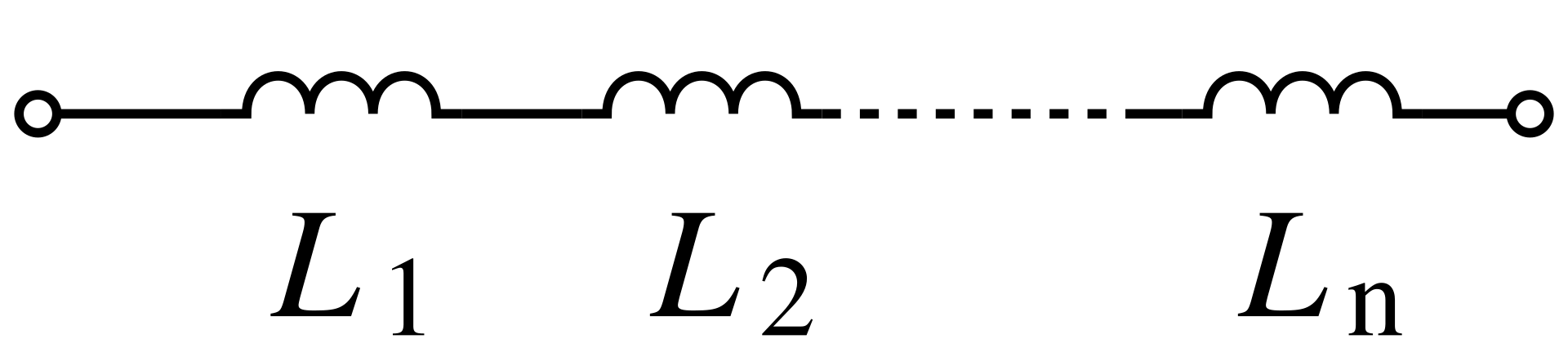
Multiple injectors when connected in an end-to-end connection with a voltage source create a series circuit.
In a series circuit, the current flowing through each component will be the same. Since the inductance is a property dependent upon the change of current in a circuit, the resultant inductance in a series circuit is the total sum of each component.
Parallel circuit
Parallel circuits are branched circuits with multiple paths of current flow. Elements in parallel connection share common nodes and the voltage drop across each component will be equal.
Equal voltage indicates that every electrical component is connected between two sets of electrically similar points. Current flowing through each branch of the circuit depends upon the component connected to that branch. If the component connected is a resistor then, a branch with low resistance will have more current flow compared to a branch with higher resistance.
Parallel circuits consist of many branches, hence removing a single component will not create an open circuit. Most measuring instruments are connected in parallel circuits. For instance, the voltmeter is connected in parallel with the component to measure the voltage.
Parallel circuits are mainly used for wiring electrical power points in buildings and automobiles. Complicated connections of high-current electrical circuits use parallel circuits. Parallel circuits are also used in designing computer hardware.
Resistor in parallel

Since parallel connections have the same voltage throughout the circuit, two or more resistors connected between two common nodes will have the same voltage. The voltage across the source will be equal to the voltage across every resistor.
The current flowing through each resistor will be different and can be calculated using Ohms law. The total current flowing through the circuit will be the sum of current flowing through each branch. Therefore,
Since the voltage across the circuit is equal to the individual voltage drop.
The voltage terms in LHS and RHS will cancel out. Therefore,
R total is the resultant resistance of the parallel circuit.
Capacitors in a parallel circuit

When individual capacitors are connected between the same terminals, that circuit will have a parallel connection. Each capacitor will have an equal voltage drop, the value will be equal to that of the voltage source.
Multiple capacitors in parallel connections act as a single capacitor. Final capacitance is the sum of the capacitance of individual components.
Inductors in a parallel circuit

Two or more inductors connected between the same set of terminals create a parallel circuit.
The voltage across parallel connection remains the same but the current changes. The inductance of a coil depends on the rate of change of current. Since each component has a different amount of current flow, the resultant voltage will not be the direct sum of individual inductances.
Current flows through the least resistant path, therefore in a parallel circuit, the batch with the least resistance will have a larger current flow. The resultant value is also dependent on the mutual inductance phenomenon.
Combination circuits
A circuit that has both series and parallel paths in combination for the electricity to flow is a combination circuit. It has properties of both types of circuits.

Context and Applications
- Bachelors in Technology (Electronics)
- Masters in Technology (Electronics)
- Bachelors in Physics
- Masters in Physics
Practice Problems
- Which of the following represents the total resistance in parallel resistors of 10 and 2000?
- 1.99
- 1.66
- 0.2
- 0.6
Answer: d
Explanation:
2. Which of the following connection allows maximum switching capacity for MOSFET?
- Parallel-connected MOSFET
- series-connected MOSFET
- series-parallel circuit connection
- None of these
Answer: a
Explanation: MOSFET in parallel connection allows maximum switching capacity.
3. What is the total voltage in a resistive parallel circuit as compared to an individual resistor?
- sum
- reciprocal sum
- equal
- none of these
Answer: c
Explanation: Total voltage in a resistive parallel circuit is equal to the resistance of an individual resistor.
4. What is the equation of total power in a resistive circuit?
- V*V
- I*I
- V/I
- VI
Answer: d
Explanation: Total power is the product of potential difference and current.
5. Find the total resistance in a circuit with two resistors of 2 ohms connected in a series circuit?
- 4
- 5
- 8.8
- 2
Answer: a
Explanation:- In a series circuit, the total resistance is the sum of resistances
Total resistance= 4
Common Mistakes
Series and parallel circuits need to be connected with a proper circuit diagram and the polarity of capacitor and inductor is to be noted. Mistakes can be made while connecting components of the circuit. Wrong electrical connections can be dangerous and may destroy the components.
Related Topics
- Electromotive forces
- DC circuits
- AC circuits
Want more help with your electrical engineering homework?
*Response times may vary by subject and question complexity. Median response time is 34 minutes for paid subscribers and may be longer for promotional offers.
Search. Solve. Succeed!
Study smarter access to millions of step-by step textbook solutions, our Q&A library, and AI powered Math Solver. Plus, you get 30 questions to ask an expert each month.
Electric Circuits and Networks
Properties of Laplace Transform
Series and Parallel circuit
Series and Parallel Circuit Homework Questions from Fellow Students
Browse our recently answered Series and Parallel Circuit homework questions.
Search. Solve. Succeed!
Study smarter access to millions of step-by step textbook solutions, our Q&A library, and AI powered Math Solver. Plus, you get 30 questions to ask an expert each month.