Crystals Around Us
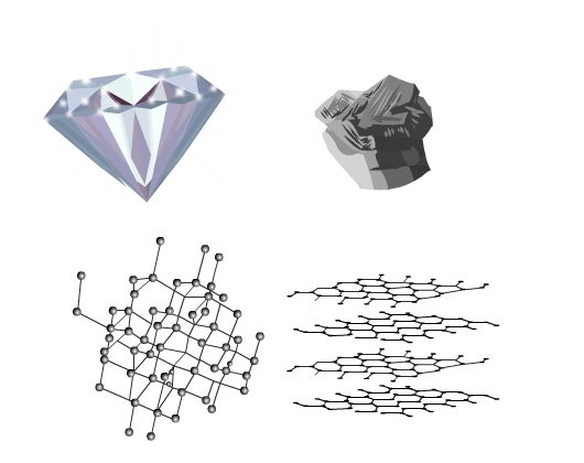
Solids are present all around us. They have different properties and applications. Diamond and graphite are two well-known solids. Diamond is the hardest material in the world and is used in making jewelry. Graphite on the other hand is soft. The lead of your pencil is graphite. Why are they so different in appearance and properties despite the fact they are chemically the same? Both are allotropes of carbon. The answer lies in the structure, the way constituent particles are arranged in the solids.
Let's explore the structure of solids.
Types of Solids
The solid-state has constituent particles (atoms, molecules, or ions) in fixed positions.
These fixed constituent particles may be arranged in a periodic (regular) or in an irregular way. Solids are therefore of two types, crystalline and amorphous. In crystalline solids (or crystals), the constituent particles have a regular arrangement. On the other hand, amorphous solids do not have any pattern in the arrangement of their constituent particles. The structure of a crystalline and an amorphous solid are shown in the figure (Fig 1) below:
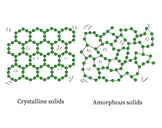
If you observe closely, the ordered arrangement in crystals represents the ordered pattern repeating over the whole crystal.
In amorphous solids regular patterns occur only in the scattered portions, the rest of it is a disordered arrangement. Sodium chloride, diamond, graphite, and quartz are examples of crystalline solids. Quartz glass, plastics, and rubber are examples of amorphous solids.
Both crystalline and amorphous solids are important in their own sense, therefore the study of their structures is important too. However, in this section, we shall focus on the structure and properties of crystalline solids only.
Graphite and diamond despite being crystals look very different and have different properties. The arrangement of particles is closely packed and 3 - dimensional in a diamond while in graphite it is a 2 - dimensional regular pattern.
Let’s delve deeper and understand the crystal structures in detail.
Properties of Crystal Structures
The properties of crystal structures are determined by the periodic arrangement of constituent particles.
- The constituent particles (atoms, molecules or ions) in a crystalline solid make a large number of small crystals which together constitute the whole crystalline solid (crystal lattice). These small crystals have a definite geometrical shape.
- Crystalline solids have a sharp melting point at a characteristic temperature.
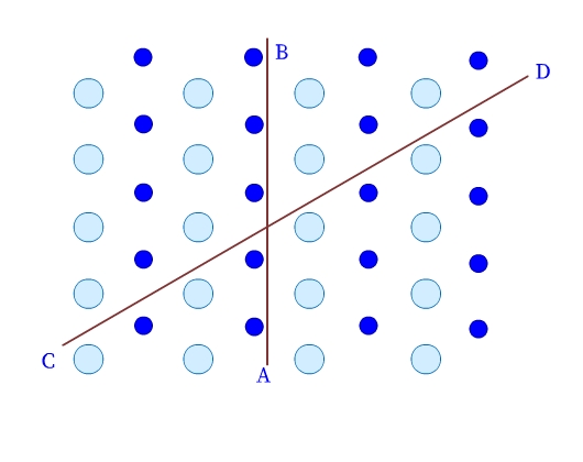
- Crystalline solids are anisotropic. Their physical properties, have different values in different directions in the same crystal. As we can see in Fig 3, the arrangement of particles in a crystalline solid is different along different directions (example, AB and CD), and therefore, the values of the measured physical properties are different too.
Crystal Lattice
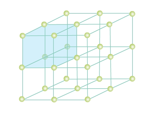
Consider a three-dimensional periodic arrangement of constituent particles in a crystal as in Fig 4. Each constituent particle is described by a point, called lattice point. This 3 - dimensional periodic and regular arrangement of points in space is called a crystal lattice.
Unit Cell
A unit cell is the smallest unit of a crystal lattice. In Fig. 4 you can see a shaded cubic box, the entire crystal can be generated by translating the shaded cube in different directions. Visualize bricks (unit cell) forming the entire wall (crystal structure) - a crystal is composed of an infinite number of such unit cells.
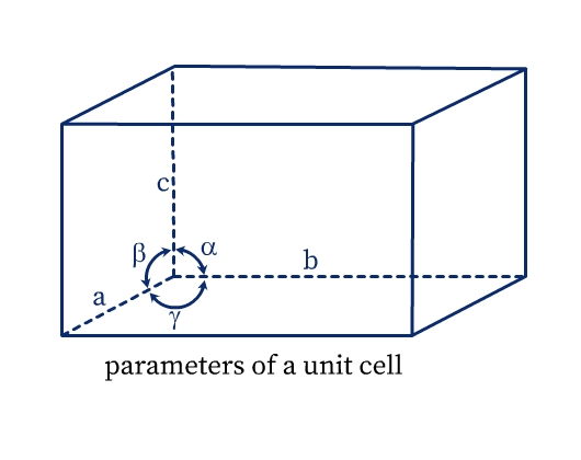
A unit cell has the following parameters (see Fig. 5):
- Dimensions of length, a, b and c along the three edges. These three edges may or may not be perpendicular to each other.
- Angles α, β, and γ which are angles between edges b and c, a and c, and a and b respectively.
Crystal Systems
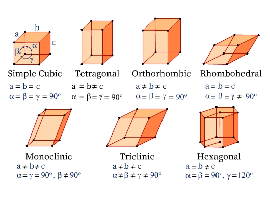
Seven Crystal Systems
There are seven crystal systems classified based on the different symmetry elements present in them. The unit cells of the seven types of crystal systems along with the relation among their unit cell parameters are illustrated in Fig 6.
Fourteen Bravais Lattices
In 1848, a French crystallographer, Auguste Bravais showed that there can be only 14 different kinds of lattices distributed among the discussed 7 crystal systems.
The unit cells can be of the following types
- Primitive (or Simple) unit cells (P): Lattice points are only at the corners of the unit cell.
- Body-centered unit cells (I): Lattice points are at the corners as well as in the center of the unit cell.
- Face centered unit cells (F): Lattice points are at the corners as well as in center of each of the faces of the unit cell.
- End-centered (or base-centered) unit cell (C): Lattice points are at the corners as well as at the centers of two parallel faces of the unit cell.
| Crystal Lattice | Bravais Lattices | |||
| Primitive (P) | Body-centered (I) | Face-centered (F) | End-Centered (C) | |
| Cubic | Yes | Yes | Yes | |
| Tetragonal | Yes | Yes | ||
| Orthorhombic | Yes | Yes | Yes | Yes |
| Rhombohedral | Yes | |||
| Monoclinic | Yes | Yes | ||
| Triclinic | Yes | |||
| Hexagonal | Yes | |||
Lattice Planes
Different sets of parallel, equally spaced planes passing through lattice points in a crystal are called crystallographic planes or lattice planes. The figure below illustrates lattice planes in two-dimensional and three-dimensional space.
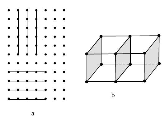
A study of the orientation and location of the lattice planes is essential to interpret X-ray diffraction by solid crystals.
X-ray Diffraction: Determination of Crystal Structures
Diffraction: Diffraction is the phenomenon of bending and spreading electromagnetic radiation when it passes through an object of the same size as its wavelength. The diffracted waves may undergo constructive interference or destructive interference depending on whether the diffracted waves are in phase (constructive interference) or out of phase (destructive interference). Constructive interference results in bright spots and destructive interference results in dark spots when observed on a photographic plate.
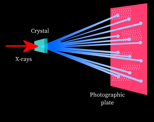
X-rays and crystal structures: X-rays are electromagnetic radiation and their wavelength is comparable to the spacing of lattice planes in crystal structures. Thus, when an X-ray is passed through a solid crystal, it diffracts. When the diffracted radiation is studied on a photographic plate, a diffraction pattern is obtained due to interference of diffracted rays (See Fig 8). This diffraction pattern is highly characteristic of the crystal structural arrangement. Thus, X-ray diffraction is used to study the structure of crystals.
Miller Indices: Identification of Lattice Planes
The location of lattice planes can be described by setting up a coordinate system. Origin is at the corner of a unit cell and the three axes x, y, and z are coinciding with the edges a, b, and c of the unit cell, respectively (see Fig 9). The distance at which the lattice plane intersects the axis is the intercept of the plane for that corresponding axis. In Fig 9a, for example, the intercepts of the triangular plane are a, b, and c along x, y, and z axes, respectively. Here, the intercepts of the plane are the same as that of the unit cell. Such a lattice plane is called a unit plane and the intercepts are called unit intercepts. In Fig 9b, intercepts of the triangular lattice plane are a/3, b/3, and c/3.
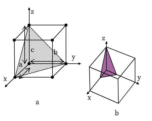
- Intercepts of the lattice planes are simply the multiples of unit cell lengths a, b and c.
- The crystal planes are labelled in terms of its Miller indices (hkl). Miller indices are a set of three numbers that indicates the orientation of planes in a crystal. Miller indices for any lattice plane are obtained by following the steps given below:
- Ratio is taken of the intercepts of plane to unit plane intercepts. The numbers so obtained are termed as Weiss indices.
- Reciprocals of these numbers are taken.
- If numbers obtained from Step 2 are in fraction form, all three numbers are multiplied by their least common multiple that gives whole numbers.
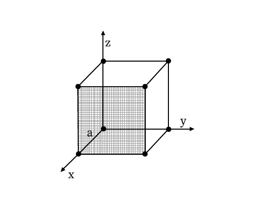
- If the plane doesn’t coincide with any axis, intercept with respect to that axis is infinity. For example, the shaded plane in Fig 10 does not coincide with y and z axis, its intercepts are therefore, a, ∞,∞.
- If an intercept is negative, the corresponding Miller index is denoted by a bar over it.
Context and Applications
The topic is useful for various undergraduate and postgraduate courses especially for Bachelors and Masters in Chemistry.
Practice Problems
Q1. Which of the following is not the property of a crystalline solid?
- Definite melting point.
- A regular arrangement of constituent particles.
- A definite geometrical shape
- Isotropic nature.
Answer: Isotropic nature
Q2. What will be the crystal system of a compound with following unit cell parameters?
a=b≠c, α=β=γ=90°
- Simple cubic
- Orthorhombic
- Tetragonal
- Rhombohedral
Answer: Tetragonal
Q3. Which of the following Bravais lattices can have the body centered unit cell?
- Cubic
- Monoclinic
- Rhombohedral
- Hexagonal
Answer: Cubic
Q4. Identify the unit cell with lattice points at the corners as well as at the centers of two parallel faces.
- Primitive unit cell
- End-centered unit cell
- Face centered unit cell
- Body-centered unit cell
Answer: End-centered unit cell
Q5. Find the Miller indices (hkl) for the planes having following intercepts:
- 2a, b, c
- -a, b, c
- a, b, ∞
Answer: a, b, c are unit plane intercepts
- Step 1: Ratio of intercepts to unit plane intercepts, we get: 2, 1, 1
Step 2: Reciprocals: ½, 1, 1
Step 3: Multiply all three numbers obtained from step 2 by 2 (least common number) to obtain whole numbers, 1, 2, 2
Miller indices are (122) - Step 1: Ratio of intercepts to unit plane intercepts, we get: -1, 1, 1
Step 2: Reciprocals: -1, 1, 1
No need of step 3 as numbers obtained from step 2 are already whole numbers
Miller indices are (1¯11) - Step 1: Ratio of intercepts to unit plane intercepts, we get: 1, 1, ∞
Step 2: Reciprocals: 1, 1, 0
No need of step 3 as numbers obtained from step 2 are already whole numbers
Miller indices are (110)
Want more help with your chemistry homework?
*Response times may vary by subject and question complexity. Median response time is 34 minutes for paid subscribers and may be longer for promotional offers.
Crystal Structures Homework Questions from Fellow Students
Browse our recently answered Crystal Structures homework questions.